-
E-mail
3440125819@qq.com
-
Phone
18911397564
-
Address
No.1 Shangdi 10th Street, Shangdi Science and Technology Park, Haidian District, Beijing
Product Categories
- Impedance analyzer
- Voltage breakdown tester
- Voltage resistance strength breakdown tester
- Semiconductor resistance tester
- Vertical specific resistance meter for metal conductive coatings
- Capillary rheometer
- Dielectric constant dielectric loss test
- Fully automatic oil medium loss and resistivity tester
- AC/DC electrical strength tester
- Voltage breakdown field strength tester
- Volume surface resistivity tester
Beijing Beiguang Jingyi Instrument Equipment Co., Ltd

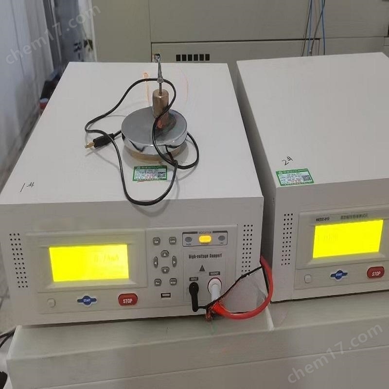
Vertical specific resistance meter for metal conductive coatings
NegotiableUpdate on 12/30
- Model
- Nature of the Manufacturer
- Producers
- Product Category
- Place of Origin
Overview
Metal conductive coating vertical resistivity meter electrode maintenance: Clean the upper and lower gold-plated electrode surfaces (wipe with ethanol) to ensure no oxidation layer or stains, and prevent contact resistance interference. $r $n pressure calibration: Check the parallelism of the pressure plate (deviation should be less than 0.025mm), pre press the empty platform to zero pressure.
Product Details
Vertical specific resistance meter for metal conductive coatings
The following are the technical points and operational specifications, as well as a comprehensive summary of core standards and practical parameters:
1、 Core principles and technical parameters
Testing principle
Place the sample between two electrodes and apply pressure (range 0.1-5MPa). Measure the vertical resistance value using the current voltage method, and automatically calculate the specific resistivity (formula: ρ=(R · A)/L, where A is the contact area and L is the coating thickness).
Key hardware configuration
Pressure system: precision screw drive (step accuracy ± 0.01MPa), equipped with digital speed regulating motor to ensure linear pressure loading.
Electrode design: Copper gold-plated electrode (diameter ≥ 16mm), contact surface flatness ≤ 0.003mm, reducing contact resistance error.
Measurement module: Resistance resolution of 0.01 μ Ω, supporting a range of 10 ⁻⁶ -10 ³ Ω, temperature drift compensation of ± 0.5%.
2、 Standardized operating procedures
Sample preparation
Clean the coating surface (wipe with anhydrous ethanol), trim the edges flat, and measure the thickness with an error of ≤ 1 μ m.
Leave it in a constant temperature and humidity environment (23 ± 2 ℃/50 ± 5% RH) for at least 2 hours to relieve stress.
Parameter Setting and Testing
Parameter itemsSet requirementsExample value
Initial pressureLight contact to avoid impact0.05MPa
Pressure step sizeIncreasing in material stiffness0.05MPa/step
holding timeDelay in reading after stable pressure5-10 seconds
termination conditionResistance change rate ≤ 2% or reaching the upper limit pressureAuto Stop
Data output
Real time display of pressure resistance curve and specific resistivity calculation results (unit: Ω· cm).
Automatically calculate range/mean and support exporting PDF reports (including temperature compensated data).
3、 Precision control and fault handling
Key points of error control
The electrode needs to be cleaned with ethanol for every 5 samples tested to prevent residual coating particles.
The sample thickness is ≥ 10 μ m (if it is too thin, it needs to be stacked for testing) to avoid the risk of breakdown.
Enable compensation algorithm when the environmental temperature and humidity exceed the standard (according to GB/T 1410-2006).
Typical troubleshooting
PhenomenonCause analysisSolution
Resistance value jumpLocal peeling of coating or electrode oxidationReplace the sample and polish the electrode
Pressure loading stagnatesInsufficient lubrication or overload of the screwAdd high-temperature lubricating grease
data driftAbnormal temperature and humidity sensorCalibration environment module
4、 Application scenarios and device selection
Core applications
Fuel cell electrode: Evaluate the conductivity uniformity of carbon paper/metal felt coating (with a dispersion coefficient ≤ 3% as qualified).
Lithium battery electrode: detect the dispersion of conductive agents, locate coating defects (range>15% indicates process abnormalities).
Quality inspection of metal coatings: Verify the consistency of resistance between sputtered/electroplated coatings (in accordance with ASTM B809 sulfur resistance requirements).
5、 Operational safety regulations
The maximum pressure must not exceed the equipment calibration value (such as 5MPa) to prevent sample fragmentation and splashing.
Wear insulated gloves during high-voltage testing, and ensure that the grounding resistance of the equipment is less than 4 Ω.
Note: Vertical specific resistance is the core indicator for evaluating the interface conductivity characteristics of metal coatings, and must strictly follow the operating logic of "environmental control step pressure real-time calibration"
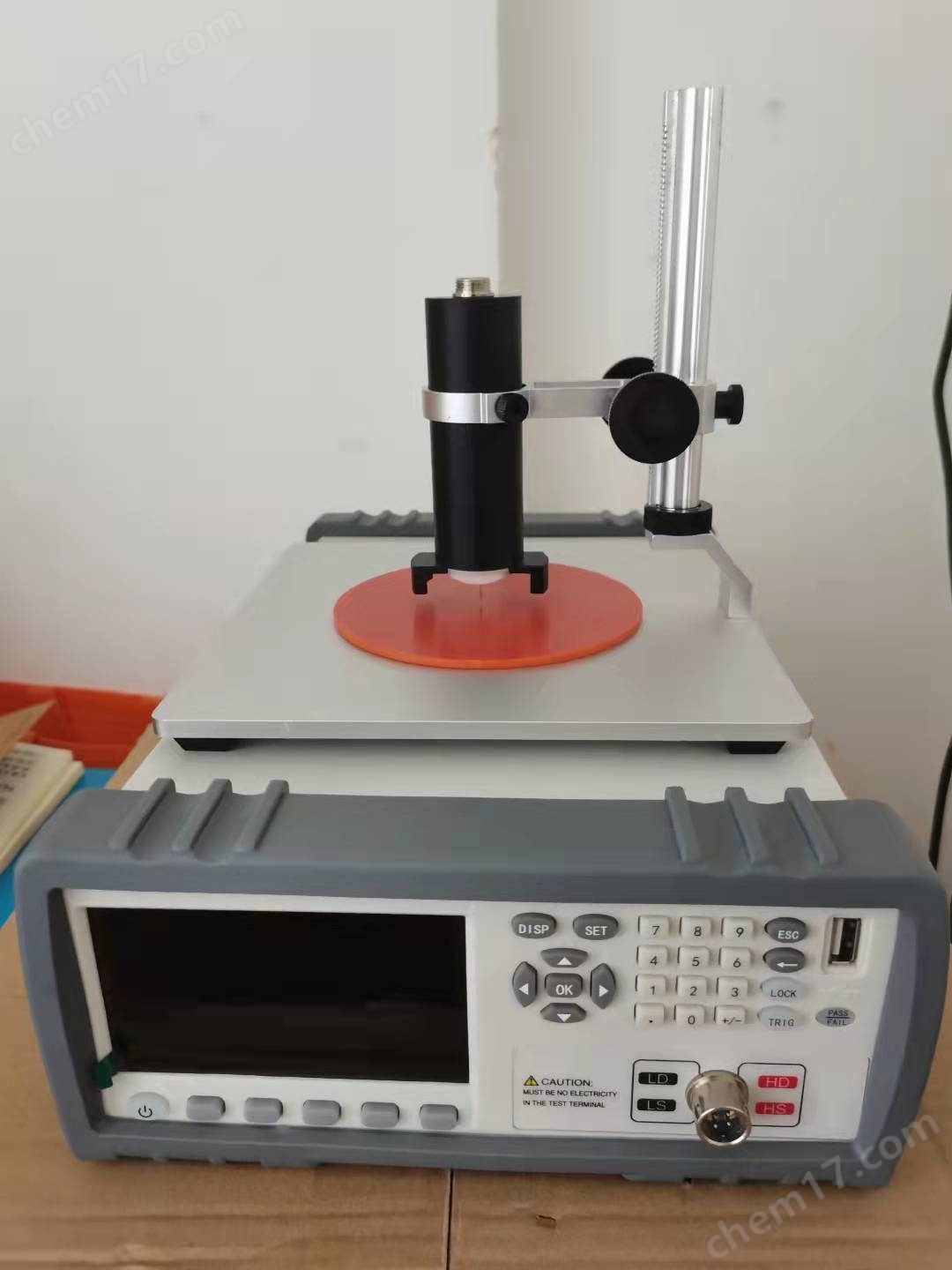
Vertical specific resistance meter for metal conductive coatings
The technical analysis and operation guide of carbon paper thickness uniformity tester for fuel cells, combined with national standards and practical experience, is compiled as follows:
1、 Testing principles and standard requirements
Core functional positioning
By using high-precision sensors for contact measurement of multi-point thickness of carbon paper, local deformation interference is eliminated, and the thickness dispersion coefficient (standard deviation/average value × 100%) is calculated to evaluate uniformity. Complies with the mandatory testing requirements of GB/T 20042.7-2014 for the consistency of carbon paper thickness in fuel cells.
Key indicator basis
Measurement point density: When the sample area is ≥ 100cm ², at least 25 uniformly distributed points (5 × 5 grid) should be selected.
Contact pressure: constant 5N/cm ² (approximately 50kPa) to avoid pressure damage to the porous structure.
Accuracy requirement: Resolution ≤ 0.1 μ m, parallelism deviation < 0.003mm.
2、 Core technical parameters of the instrument
Components/Functions Technical specifications Function
Sensors Micro displacement sensor (accuracy ± 0.5 μ m) Capture small fluctuations in thickness
Foot measurement design Diameter 16mm, contact area 200mm ² Disperse pressure and protect porous structures
Automatic calculation of mean/standard deviation/dispersion coefficient for data output, supporting micro printing Quickly generate detection reports
Environmental adaptability temperature and humidity monitoring (23 ± 2 ℃, 50 ± 5% RH) with built-in zero calibration Eliminate environmental interference
3、 Standardized operating procedures
Sample pretreatment
Cut into 100mm x 100mm standard size, with no burrs on the edges.
Stress relief should be achieved by standing in a constant temperature and humidity environment (23 ℃/50% RH) for at least 4 hours.
Equipment calibration
Before each test, calibrate the zero point with a standard measuring block, and retest each group of samples afterwards.
Verify the parallelism of the pressure plate (deviation ≤ 0.025mm).
Thickness measurement
1. Place the sample in the center and gently lower the foot to the contact surface
2. Maintain a pressure of 5N/cm ² for 3 seconds to obtain a stable reading
3. Complete 25 point measurements in grid order (to avoid duplicate positions)
4. The device automatically generates a thickness distribution cloud map and statistical parameters
4、 Key precautions
Error control
Foot cleaning: Wipe residual carbon fibers with ethanol to prevent lifting of virtual values.
Speed control: Measure foot descent speed ≤ 2mm/s to avoid impact deformation.
Invalid data exclusion: When the measuring point is located at a fold or damaged area, it needs to be remeasured.
Result validity assessment
Dispersion coefficient ≤ 3%: meets the carbon paper standard for automotive fuel cells.
Thickness range>10 μ m: indicates material process defects (such as uneven impregnation).
5、 Application scenario extension
Process optimization
Using thickness distribution cloud maps to locate production defects (such as uneven coating) and guide the adjustment of impregnation processes.
New material research and development
Compare the thickness changes before and after PTFE coating to evaluate the uniformity of the waterproof layer.
Quality traceability
Bind thickness data and batch number to establish a carbon paper lifespan prediction model.
Dynamic response: Current loading rate ≥ 100A/s, simulating vehicle start stop conditions.
Special analysis of membrane electrode
Platinum loading test: X-ray fluorescence method (non-destructive), accuracy ± 0.01mg/cm ².
Ohmic polarization: Four wire method for measuring the contact resistance of membrane electrodes, with a resolution of 0.01m Ω· cm ².
Durability assessment: Accelerated aging test (reverse polarity/chemical corrosion/wet dry cycle).
What are the key testing parameters of a fuel cell tester?
Wuxi Hydrogen Core Technology Co., Ltd
Chinese Electrotechnical Society Group Standard: Performance Testing Method for Proton Exchange Membrane Fuel Cell Stack for Vehicles
Journal of Electrical Technology
2、 Standardized operating procedures
1. Preparation before testing
Assembly of fuel cell stack:
The bipolar plate and membrane electrode stack need to be clamped in the center, with the rough surface of the carbon paper facing the smooth surface of the flow channel facing the proton membrane.
Tighten the bolts step by step with a torque wrench (e.g. 2N · m → 4N · m), and load in diagonal order to avoid uneven loading.
Airtightness verification: A nitrogen pressure of 50kPa and a pressure drop of ≤ 1kPa/min are considered qualified.
2. Key parameter settings
Testing module Key points for parameter setting Example value
polarization curve Current scanning step size ≤ 0.1A/cm ², stable current time at each point ≥ 30s 0.05A/cm ² step size
EIS impedance spectrum Sinusoidal amplitude=DC current x 5%, frequency points/harmonics ≥ 10 100mA amplitude, 10 points/frequency
Activation process Constant current stage (0.2A/cm ²)+cyclic voltammetry (0.1~0.9V) 3-hour activation
3. Fault diagnosis and optimization
Abnormal water management:
Voltage oscillation Check the humidity sensor or adjust the gas dew point 3.
Low frequency impedance increase Optimize the drainage design of the flow field plate 28.
Catalyst decay:
ECA (electrochemical active area) decreases by more than 20% → triggering reverse polarity protection protocol 57.
III. Safety and Accuracy Control
Operating standards
Before hydrogen testing, it is necessary to Three nitrogen replacements, concentration sensor threshold set ≤ 1% LEL.
Wear 10kV insulated gloves when measuring high voltage (>60V), and the grounding resistance of the equipment should be less than 4 Ω.
Data calibration
Principle of vertical resistivity testing
The sample is placed between two parallel electrodes and subjected to controllable pressure in the vertical direction (such as 0.05~4.0MPa). The resistance values at different pressures are measured in real time using the four terminal method. The formula for calculating the resistivity is: ρ=(R × S)/L (where ρ is the resistivity, R is the resistance, S is the electrode contact area, and L is the sample thickness).
Technical advantages: Eliminating the influence of contact resistance, supporting continuous measurement under dynamic pressure, and accurately reflecting the conductivity of materials in a compressed state.
Core measurement capability
Pressure control: range 30-5000N (≈ 0.05-4.0MPa), resolution 0.1N, accuracy ± 0.5%;
Resistance measurement: range 1 μ Ω -20k Ω, resolution up to 0.01 μ Ω, supports automatic temperature compensation;
Motion control: precision screw drive, adjustable speed from 1-300mm/min, ensuring smooth pressure loading.
2、 Key application scenarios
1. Evaluation of New Energy Battery Materials
Proton Exchange Membrane Fuel Cell (PEMFC):
Test the vertical resistivity of carbon paper (gas diffusion layer) and bipolar plate under simulated battery assembly pressure, and optimize the conductive coating process.
Electrode of flow battery:
According to standard T/CEEIA 577-2022, evaluate the Z-directional conductivity of electrode materials for iron chromium flow batteries.
2. Research and quality inspection of special materials
Verification of vertical conductivity performance of copper foil coating and nitride ceramic coating for coating/film materials;
Porous carbon materials: Consistency testing of electrical resistivity under loose packing density of carbon fiber paper (e.g. GB/T 24525-2009);
Powder material: Analysis of the resistivity change curve of lithium battery positive electrode powder during compaction process.
3、 Precautions for operation and selection
Test key control points
Uniformity of pressure: The parallelism of the upper and lower pressure plates should be less than 0.025mm to avoid data distortion caused by unbalanced loading;
Electrode maintenance: Copper plated electrodes need to be cleaned regularly (wiped with ethanol) to prevent the increase of contact resistance caused by the oxide layer;
Environmental calibration: High temperature testing requires the configuration of platinum electrodes and the recording of temperature drift effects.
4、 Technological Evolution Direction
Intelligent expansion:
The new generation of equipment integrates PC software (such as Hengpin), which can export pressure resistivity three-dimensional maps and assist in the construction of material compression models;
Multi parameter joint testing:
Combining deformation sensors to synchronously record changes in sample thickness and analyze the correlation between compaction density and resistivity (such as optimizing battery electrode processes).
The vertical resistance tester has become a core equipment for the development of new energy materials through the integration of precision pressure control and electrical measurement. Its resistivity data under dynamic pressure is crucial for improving battery performance.