-
E-mail
3440125819@qq.com
-
Phone
18911397564
-
Address
No.1 Shangdi 10th Street, Shangdi Science and Technology Park, Haidian District, Beijing
Product Categories
- Impedance analyzer
- Voltage breakdown tester
- Voltage resistance strength breakdown tester
- Semiconductor resistance tester
- Vertical specific resistance meter for metal conductive coatings
- Capillary rheometer
- Dielectric constant dielectric loss test
- Fully automatic oil medium loss and resistivity tester
- AC/DC electrical strength tester
- Voltage breakdown field strength tester
- Volume surface resistivity tester
Beijing Beiguang Jingyi Instrument Equipment Co., Ltd
AC/DC withstand voltage and resistance tester
NegotiableUpdate on 12/30
- Model
- Nature of the Manufacturer
- Producers
- Product Category
- Place of Origin
Overview
Important reminder for AC/DC withstand voltage and resistance tester: Please refer to your equipment manual and the corresponding safety standards (such as IEC 60335) for specific operation. Incorrect setting of test parameters may lead to safety accidents or misjudgments! Through the above standardized process, $r $n $r $n can ensure the accuracy of test results and the safety of operators to the maximum extent possible. In case of complex scenarios (such as medical equipment, high-voltage cables), special testing specifications must be followed.
Product Details
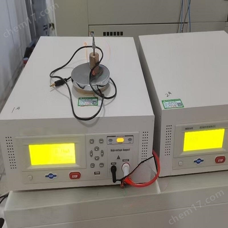
BDAT-921AC/DC withstand voltage and resistance tester
1feature
1.High power AC withstand voltage test
2.DC withstand voltage test
3.Insulation resistance test
4.Grounding resistance test
5.Conductivity test
6.Leakage current test
7.Electrical performance testing
IITechnical Specifications
AC/DC withstand voltage and resistance tester | ||||
|
output voltage |
AC |
scope |
0.05 - 5.0kV |
|
waveform |
50/60Hz ± 0.1% sine wave |
|||
output power |
500VA(5.0kV/100mA) |
|||
DC |
scope |
0.05 - 6.0kV |
||
output power |
150VA(6.0kV/25mA) |
|||
Load variation rate |
± (1% set value+10V) (rated power) |
|||
resolution |
2V |
|||
precision |
± (1% set value+5V) |
|||
Current testing |
AC |
scope |
V≤4kV |
0.001mA-120mA |
V>4kV |
0.001mA-100mA |
|||
resolution |
0.001mA |
|||
precision |
120mA |
0.1mA-120.0mA ± (1% reading+0.6mA) |
||
30mA |
0.01mA-29.99mA ± (1% reading+0.15mA) |
|||
3mA |
0.001mA-2.999mA ± (1% reading+0.015mA) |
|||
DC |
scope |
V≤1.5kV |
0.0001mA-25mA |
|
V>1.5kV |
0.0001mA-20mA |
|||
resolution |
0.1μA |
|||
precision |
25mA |
0.01mA-25.00mA ± (1% reading+0.12mA) |
||
3mA |
0.001mA-2.999mA ± (1% reading+0.015mA) |
|||
5.1μA |
±0.1μA-299.9μA(1% reading+1.5μA) |
|||
|
Time Setting |
Test time |
0.3 - 999s , 0 represents continuous testing |
||
rise time |
0.1 - 999s , 0 means closed |
|||
fall time |
0.1 - 999s , 0 means closed |
|||
waiting time |
0.1 - 999s , 0 means closed (only DC withstand voltage) |
|||
Arc detection |
AC |
1.0mA -20.0mA |
||
DC |
1.0mA - 10.0mA |
|||
Maximum short-circuit current AC test |
200mA |
|||
Quick discharge function |
Automatic discharge after the test is completed(DCW) |
|||
Insulation resistance test | ||||
|
voltage |
output |
DC:0.05 - 5.0kV |
||
resolution |
2V |
|||
precision |
± (1% reading+5V) |
|||
|
resistance |
test scope |
0.1MΩ - 50.0GΩ |
||
|
test precision |
V≥500V |
1MΩ - 1GΩ |
± (3% reading+1M) |
|
1GΩ - 10GΩ |
± (7% reading+0.2G) |
|||
10GΩ - 50GΩ |
± (10% reading+0.5G) |
|||
V<500V |
1MΩ - 1GΩ |
± (5% reading+100V/Vs * 10M) |
||
|
Time Setting |
Test time |
0.3 - 999s , 0 represents continuous testing |
||
rise time |
0.1 - 999s , 0 means closed |
|||
fall time |
0.1 - 999s , 0 means closed |
|||
waiting time |
0.1 - 999s , 0 means closed |
|||
Quick discharge function |
Automatic discharge after the test is completed |
|||
Leakage current test | ||||||
power supply |
scope |
0 - 277Vac,16Aac Max |
||||
precision |
± (1.5% reading+2 words) (30-277V) |
|||||
leakage current |
test scope |
0.0μA to 10.00mA |
||||
test frequency |
DC ,15Hz - 1MHz |
|||||
Test time |
AC+DC |
0.5 - 999s , 0 represents continuous testing |
||||
AC/DC |
0.1 - 999s , 0 represents continuous testing |
|||||
waiting time |
AC+DC |
0.5 - 999s |
||||
AC/DC |
1.8-999s automatic range |
|||||
1.3-999s fixed range | ||||||
|
Human impedance network MD |
A: |
UL544NP, UL484, IEC60598, UL1363, UL923, UL471, UL867, UL697 |
||||
B: |
UL544P |
|||||
C: |
UL2601 - 1 、IEC60601 - 1 、EN60601 - 1 |
|||||
D: |
UL1563 |
|||||
E: |
IEC60990Fig4U2 、IEC60950 - 1 、IEC60335 - 1 、IEC60598 - 1 、UL484、 IEC60065 、IEC61010 |
|||||
F: |
IEC60990Fig5U3 、IEC60598 - 1 |
|||||
G: |
Frequency detection1kΩ |
|||||
|
MDA-G devices precision |
Resistance accuracy |
±1% |
||||
Capacitor accuracy |
±5% |
|||||
MD voltage protection |
30V peak or 30Vdc |
|||||
Probe settings |
G-L 、PH-L 、PH-PL |
|||||
|
Leakage current range valid valueRMS |
MD main resistor |
scope |
||||
0.5kΩ/1kΩ/ 1.5kΩ |
0.0μA-10.00mA |
|||||
|
resolution |
auto-ranging& Fixed range1-2& Fixed range3(1k&1.5kMD) |
<1000μA |
0.1μA |
|||
1000μA-8400μA |
1μA |
|||||
>8400μA |
0.01mA |
|||||
Fixed range3 (0.5kMD)&Fixed Range 4-6 |
<8400μA |
1μA |
||||
>8400μA |
0.01mA |
|||||
|
range precision |
range |
Measurement Mode |
frequency |
precision |
||
|
range 1 - 5 |
AC+DC |
DC |
± (2% reading+3 words) |
|||
15Hz<f<100kHz |
± (2% reading+3 words) |
|||||
100kHz≤f≤1MHz |
± (5% reading)>10.0 μ A |
|||||
onlyAC |
15Hz<f≤30Hz |
± (3% reading value+5 words) |
||||
30Hz<f<100kHz |
± (2% reading+3 words) |
|||||
100kHz≤f≤1MHz |
± (5% reading)>10.0 μ A |
|||||
onlyDC |
DC |
± (2% reading+3 words)>10.0 μ A |
||||
|
range6 |
AC+DC |
DC |
± (5% reading)>10.0 μ A
|
|||
15Hz<f<100kHz | ||||||
onlyAC |
15Hz<f≤30Hz |
|||||
30Hz<f<100kHz | ||||||
onlyDC |
DC |
|||||
|
Leakage current range peakPEAK |
MD main resistor |
scope |
||||
0.5kΩ / 1kΩ / 1.5kΩ |
0.0μA to 10.00mA |
|||||
|
resolution |
auto-ranging& Fixed range1-2& Fixed range3(1k&1.5kMD) |
<1000μA |
0.1μA |
|||
1000μA - 8400μA |
1μA |
|||||
>8400μA |
0.01mA |
|||||
|
Fixed range3(0.5kMD)& Fixed range4-6 |
<8400μA |
1μA |
||||
>8400μA |
0.01mA |
|||||
|
range precision |
range |
test mode |
frequency |
precision |
||
range 1-5 |
AC+DC |
DC |
± (2% reading+2 μ A) |
|||
15Hz≤f≤1MHz |
± (10% reading+2 μ A) |
|||||
onlyAC |
15Hz<f<1MHz |
± (10% reading+2 μ A) |
||||
range6 |
AC+DC |
DC |
± (2% reading+3 words) |
|||
15Hz<f<100kHz |
± (10% read value+2 words) |
|||||
onlyAC |
15Hz<f<100kHz |
± (10% read value+2 words) |
||||
|
Leakage voltage range valid valueRMS |
MD main resistor |
scope |
|||
0.5kΩ / 1kΩ / 1.5kΩ |
0.0mV - 15.00V |
||||
|
resolution |
auto-ranging& Fixed range1 - 2& Fixed range3(1k&1.5kMD) |
<1000mV |
0.1mV |
||
1000mV - 8400mV |
1mV |
||||
>8400mV |
0.01V |
||||
Fixed range3 (0.5kMD)&Fixed Range 4-6 |
<8400mV |
1mV |
|||
>8400mV |
0.01V |
||||
|
range precision |
range |
test mode |
frequency |
precision |
|
|
range 1-5 |
AC+DC |
DC |
± (2% reading+3 words) |
||
15Hz<f<100kHz |
± (2% reading+3 words) |
||||
100kHz≤f≤1MHz |
± (5% reading)>10.0mV |
||||
onlyAC |
15Hz<f≤30Hz |
± (3% reading value+5 words) |
|||
30Hz<f<100kHz |
± (2% reading+3 words) |
||||
100kHz≤f≤1MHz |
± (5% reading)>10.0mV |
||||
onlyDC |
DC |
± (2% reading+3 words)>10.0mV |
|||
|
range6 |
AC+DC |
DC |
± (5% reading)>10.0mV |
||
15Hz<f<100kHz | |||||
onlyAC |
15Hz<f≤30Hz |
||||
30Hz<f<100kHz | |||||
onlyDC |
DC |
||||
|
Leakage voltage range peakPEAK |
MD main resistor |
scope |
|||
0.5kΩ / 1kΩ / 1.5kΩ |
0.0mV - 15.00V |
||||
|
resolution |
auto-ranging& Fixed range1 - 2& Fixed range3(1k&1.5kMD) |
<1000mV |
0.1mV |
||
1000mV - 8400mV |
1mV |
||||
>8400mV |
0.01V |
||||
Fixed range3 (0.5kMD)&Fixed Range 4-6 |
<8400mV |
1mV |
|||
>8400mV |
0.01V |
||||
|
range precision |
range |
test mode |
frequency |
precision |
|
range 1-5 |
AC+DC |
DC |
± (2% reading+2mV) |
||
15Hz≤f≤1MHz |
± (10% reading+2mV) |
||||
onlyAC |
15Hz<f<1MHz |
± (10% reading+2mV) |
|||
range6 |
AC+DC |
DC |
± (2% reading+3 words) |
||
15Hz<f<100kHz |
± (10% read value+2 words) |
||||
onlyAC |
15Hz<f<100kHz |
± (10% read value+2 words) |
|||
OSC short circuit detection | |||||
Sampling standard capacitance range |
0.001 - 40nF |
||||
Open circuit judgment range |
10% - 100% |
||||
Short circuit judgment range |
100% - 500% |
||||
Security protection function | |||||
Electric shock protection |
0.5mA ± 0.25mA selectable: on or off |
||||
Activation ProtectionInterlock |
Pin low is required to allow high voltage output |
||||
Panel operation protection |
Key lock |
||||
alarm indication |
qualifiedShort tone, green light; Unqualified: Long tone, red light |
||||
Electrical and leakage power short circuit protection |
23ARMS or impulse current 68APEAK |
||||
Voltage withstand and ground synchronous output test |
5kVac/30mAac 和30 Aac/150mΩ(TH9131/TH9131A) |
||||
Storage and Interface | |||||
Internal memory |
storable100 files, each file can edit 50 steps |
||||
Standard interface |
RS232 、USB DEVICE 、USB HOST 、LAN 、HANDLER |
||||
Optional interface |
GPIB |
||||
Environmental temperature and humidity | |||||
Parameter comparison temperature |
18 ℃ -28 ℃, humidity: 30% -70% RH |
||||
Normal operating temperature |
0 ℃ -45 ℃, humidity: 20% -90% RH |
||||
Storage environment temperature |
-10 ℃ -55 ℃, humidity:<80% RH |
||||
General indicators | |||||
power supply |
100V - 240VAC ,47Hz - 63Hz |
||||
power |
no-load:<100W, Rated power: 1200W |
||||
Volume(W)×(H)×(D) |
430mm ×132mm ×550mm |
||||
weight |
40kg |
||||
The following is an insulation resistance withstand voltage tester (integrated insulation resistance test)+The standard usage process of the voltage withstand test function, combined with safety operation specifications and technical points, is provided for your reference:
1、 Preparation before testing with insulation resistance withstand voltage tester
1. Environmental confirmation
Ambient temperature10℃~30℃ (to avoid temperature affecting accuracy)
Humidity:≤75% RH(Wet environment can easily lead to increased surface leakage current)
No strong electromagnetic interference, no flammable or explosive materials
2. Equipment inspection
The appearance of the instrument is intact, the high-voltage wire is not damaged, and the grounding wire is firm
Confirm the validity period of instrument calibration (usually requiring annual calibration)
Connect the test line in a power-off state
3. Tested equipment(DUT)Prepare
Power off and discharge: disconnectDUTAll external power sources discharge capacitive components (such as power filter capacitors)
Cleaning: Remove surface dust and oil stains (avoid crawling)
Disconnect unrelated lines: Remove external connection lines (such as communication lines, load lines)
4. Personal protection
Wear insulated gloves(≥CAT IIILevel)
Standing on an insulated rubber pad
Set up a warning zone and hang it upWarning sign for "High Voltage Test"
2、 Connection of test line for insulation resistance withstand voltage tester
>Core principle: High voltage end(H)→ Tested conductor; Grounding terminal(G/L)→ Metal shell/Safely located
Insulation voltage tester
∝ - High voltage output line (red) → ConnectedDUTLive parts (such asL/NShort circuited terminal)
∝ - Return Line/Grounding wire (black) → GroundingDUTMetal casing or grounding terminal
└ - Grounding terminal (yellow green) → Connect to an independent grounding post (not mixed with the neutral wire!)
Notes:
During the withstand voltage test: if tested The input circuit needs to be connected to the casingL/NShort circuit the terminal and connect it to the high voltage end, then connect the casing to the return end
During insulation resistance testing: the wiring is the same, but usually needs to be disconnectedDUTInternal grounding (according to standard requirements)
3、 Parameter settings
1. Voltage withstand test mode(AC/DC HiPot)
|Parameters|Setting criteria|Typical Value Example
|Test voltage|Product safety standards (such asGB 4706.1)| 1500V AC (Basic insulation of household appliances) |
|Testing time|Standard regulations (commonly used in production)1~3Seconds)| 60Second (Type Test)
|Leakage current upper limit|Standard limits (such asClass IEquipment ≤5mA)| 3.0 mA(Leave a margin)
|Slow rise time|Reduce impact (standards may require)5Seconds)| 5Second|
|Alarm mode|Stop immediately upon exceeding the limit| ON |
2. Insulation resistance testing mode
|Parameters|Setting criteria|Typical Value Example|
|Test voltage|Standard regulations (such as500V DC)| 500V (low-voltage equipment) |
|Testing time|Stable reading (≥)30Seconds)| 60Second|
|Qualified threshold|Standard limits (such as ≥)2MΩ)| 100MΩ (Enterprise Internal Control)|
4、 Safe boot test
1. Turn on the instrument power, enter standby mode after passing the self-test
2. Initiate contact check (if any):
Function: Check if the test line is in good contact
Operation: Press`CONTACT CHECK`Key, confirm none“Open Circuit”Alarm
3. Safety confirmation:
Close the protective door of the testing area (trigger safety interlock)
Loud warning:High voltage test started
4. Perform testing:
Manual mode: Press`TEST`Button
Automatic mode: triggers remote start signal (for production line)
5、 Monitoring during testing
|Phenomenon|Possible reasons|Response measures
|Sudden increase in leakage current>upper limit|Insulation breakdown/Flashing over|The instrument automatically cuts off high voltage and recordsFAIL |
|The current slowly rises|Insulation that is damp or dirty|Continuous observation, stop immediately upon exceeding the limit|
|Instrument alarm "overload"|Insufficient output capacity (large capacitive load)|Switch to a higher power model orDCTesting|
|Test line ignition/Abnormal noise|Air breakdown or poor connection|Urgent pressSTOPThe key! Check the connection|
6、 Operation after testing
1. Discharge:
DCTesting or capacitive load: waiting30For more than a second, use a discharge rod to touch the high voltage end and discharge it to the casing
Confirm that the instrument displays zero voltage(<5V)
2. Disconnect:
Remove the high-voltage line first → Disassemble the return line again → Finally remove the grounding wire
3. Result record:
Save data:PASS/FAILLeakage current value, insulation resistance value (if applicable)
Print or export to quality system (with timestamp)
7、 Key safety prohibitions
Prohibition: One handed operation, wet hand operation, and moving wires during testing
Prohibition: Skip the grounding step or use damaged test wires
Prohibited: inDUTTest under powered on state
Emergency situation: Immediately press the red emergency stop button on the instrument!
8、 Maintenance points
|Cycle|Operation|
|Daily|Clean the surface of the instrument and check the cables|
|Monthly|Calibrate the zero point of leakage current (using a calibration box)|
|Every year|Send the metrology institution for comprehensive calibration|
|After the malfunction|Stop using and label as' awaiting repair '|


