-
E-mail
3440125819@qq.com
-
Phone
18911397564
-
Address
No.1 Shangdi 10th Street, Shangdi Science and Technology Park, Haidian District, Beijing
Product Categories
- Impedance analyzer
- Voltage breakdown tester
- Voltage resistance strength breakdown tester
- Semiconductor resistance tester
- Vertical specific resistance meter for metal conductive coatings
- Capillary rheometer
- Dielectric constant dielectric loss test
- Fully automatic oil medium loss and resistivity tester
- AC/DC electrical strength tester
- Voltage breakdown field strength tester
- Volume surface resistivity tester
Beijing Beiguang Jingyi Instrument Equipment Co., Ltd

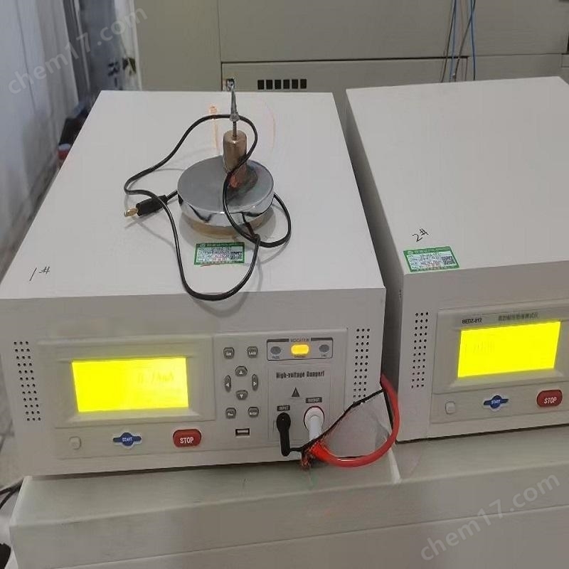
Insulation oil medium and volume resistivity tester
NegotiableUpdate on 12/30
- Model
- Nature of the Manufacturer
- Producers
- Product Category
- Place of Origin
Overview
Overview of Insulation Oil Dielectric and Volume resistivity Tester The insulation oil dielectric loss and resistivity tester is a high-precision integrated testing instrument designed and manufactured based on GB/T5564-2007 "Measurement of Relative permittivity, dielectric loss factor, and DC resistivity of liquid insulation materials".
Product Details
Insulation oil medium and volume resistivity tester
Insulation oil medium and volume resistivity tester
Power consumption: 100W
Total weight: 21Kg
In the interface of Figure 3, click on the empty cup test to enter Figure 6. The empty cup test mainly verifies the cleanliness and assembly of the oil cup before oil injection. You can choose the dielectric loss factor, relative permittivity, and volume resistivity. Click the cursor in front of the test item to select whether to test or not to test.
Power consumption<200 W
Measurement signal socket is used to plug in measurement signal wires
plate spacing2mmOil cup capacity40ml
Place the insulating ring (6) into the shielding electrode (4).
DC resistivity ranging from 2.5 M Ω m to 20 T Ω m
Assembly method (disassembly steps reversed)
Dimensions: 420mm * 380mm * 385mm
The cleaned parts must not be directly touched by hand. Silk gloves must be worn during assembly, and the following steps must be followed for assembly.
Click on the data query in Figure 3 to enter the interface in Figure 8. Click on the previous and next pages to browse, or click on print to print the data; You can also click the delete button to delete the data, and press the exit button to return to the main interface.
After the empty cup detection is completed and there are no problems, take out the inner electrode of the oil cup and place it on the cup holder. Take 40ml of the oil sample to be tested and place it in the oil cup (note: when injecting the oil sample, be sure not to have bubbles and slowly inject along the cup wall). After injecting the oil sample, slowly place the inner electrode of the oil cup in place. (The movement should be slower to prevent the oil sample from overflowing due to too fast movement and delayed exhaust), connect the measurement signal line and temperature signal line, click on the automatic test in Figure 3, and enter the interface in Figure 6 and Figure 7. Generally, oil is measured at 90 ℃ according to the regulations, but you can also choose to test immediately and measure at the current temperature.
After setting, click OK to return to the main interface in Figure 3.
Measurement range: capacitance 5pF~200pF, relative permittivity 1.000~30.000
Resolution: capacitance 0.01pF, relative permittivity 0.001, dielectric loss factor 0.00001
Temperature measurement range: 0-125 ℃
Place a clean oil cup in the cup groove (note that the inner and outer electrodes of the oil cup must be placed in place), and connect the measurement signal line and temperature signal line as shown in Figure 2. The temperature signal wire is placed in the socket at the center of the oil cup.
The power socket and switch are well connected to the AC 220V 50Hz power cord; Power switch controls the on/off of instrument power supply
Measurement accuracy: capacitance ± (1% reading+0.5pF) relative permittivity ± 1% reading dielectric loss factor ± (1% reading+0.0001) DC resistivity ± 10% reading
AC experiment voltage: continuously adjustable from 0 to 2000V, frequency 50Hz
The oil cup groove is used to place the test oil cup
Both are placed on the low-voltage electrode (2).
DC test voltage: 0-500V continuously adjustable
Temperature measurement error: ± 0.5 ℃
Dielectric loss factor 0.00001~100
Panel Instructions
Cleaning and installation methods for oil cups
Diagram of Operation Steps
Reliable ground wire connection post for grounding pole
Working power supply AC 220V (1 ± 10%)
Technical specifications of oil cup
Empty cup capacitance60±5pFEmpty cup dielectric loss value<5×10⁻⁵
Tighten the low-voltage electrode nut (3) onto the low-voltage electrode (2).
The LCD screen displays relevant information such as date, time, operating parameters, test results, and operation menu prompts; The average value of single and multiple test results printed by the printer;
Place the insulating ring (7) onto the shielding electrode (4).
Tighten the shield electrode nut (5) onto the shield electrode (4).
In the interface of Figure 4, the experimental parameters can be set separately. The figure shows the default parameters of the device. If you need to change them, simply click on the parameter you want to change, and a small keyboard will automatically pop up, as shown in Figure 5. Enter the required parameters directly on the keyboard and click the confirm button on the keyboard. When selecting to print, simply click on the cursor to switch between yes and no.
Relative humidity ≤ 80%
After opening the temperature signal line, insert or remove the oil cup and close it before testing can be carried out;
The smaller the dielectric loss value of the empty cup, the better. After selecting the test item in Figure 6 and clicking OK, you can enter Figure 7. The equipment in Figure 7 can be measured at the set 90 ℃, or you can click Test Now to measure at the current temperature.
Environmental temperature 0-40 ℃
Power frequency 50 Hz (1 ± 10%)
Connect the ground wire to the device properly, connect the power cord, turn on the power switch, and the device will automatically enter the main interface
Usage conditions
In the interface of Figure 3, press the test condition key to enter the next level menu of the device