-
E-mail
panyue@sourcescn.com
-
Phone
13475860763
-
Address
501, Building 57, Optics Valley Software Park, 396 Emeishan Road, Huangdao District, Qingdao City, Shandong Province
Product Categories
Qingdao Senquan Optoelectronics Co., Ltd
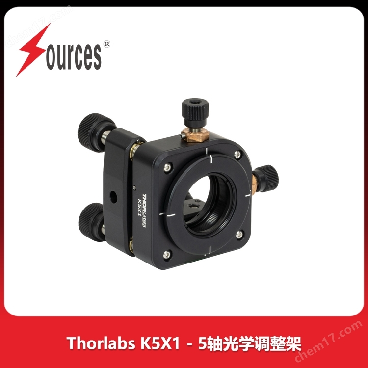
Thorlabs K5X1-5 axis optical adjustment bracket
NegotiableUpdate on 12/13
- Model
- Nature of the Manufacturer
- Producers
- Product Category
- Place of Origin
Overview
Thorlabs K5X1-5 axis optical adjustment bracket $r $n is used for 1/2 inch, 1 inch or; Adjustment bracket $r $n for 2-inch optical components with SM05 (0.535 "-40), SM1 (1.035" -40), or SM2 (2.035 "-40) internal threads $r $n pitch, yaw, and XYZ adjustment
Product Details
Thorlabs K5X1-5 axis optical adjustment bracketimage:

Thorlabs K5X1-5 axis optical adjustment bracketFeatures:
Adjustment bracket for Ø 1/2 inch, Ø 1 inch, or Ø 2 inch optical components
Equipped with SM05 (0.535 '-40), SM1 (1.035' -40) or SM2 (2.035 '-40) internal threads
Pitch, yaw, and XYZ adjustment
The optical component mounting slots of these 5-axis optical adjustment frames can be adjusted along 5 axes (pitch, yaw, and XYZ). The optical component installation slots of the adjustment frame have internal threads SM05 (0.535 '-40), SM1 (1.035' -40), or SM2 (2.035 '-40) for fixing the installed optical components. Adjustment bracket attachedSM05RRTheSM1RRorSM2RRCollar, used to secure uninstalled optical components.
The three adjusters used for pitch, yaw, and Z-translation in K5X05 can be independently locked, while the X-axis and Y-axis cannot be locked. There are locking screws on all five adjusters of K5X1 and K5X2. KC5X1 (/M) requiresF19SC1Lock ring (sold separately) to lock the X-axis or Y-axis, requiredF25SC1Lock ring (sold separately) to lock Z-axis, pitch or yaw.
The adjustment frame is engraved with vertical and horizontal lines, used as an alignment aid for optical component slots.
K5X05, K5X1, K5X2, and KC5X1 (/M) can be installed in both left and right hand directions; K5X05 and K5X1 have two orthogonal # 8 (M4) countersunk holes, while K5X2 has two orthogonal mounting surfaces with three # 8 (M4) countersunk holes on each surface (a total of six). The KC5X1 (/M) has two orthogonal 8-32 (M4 x 0.7) mounting holes and four through holes for Ø 6 mm ER cage bars to be compatible with our 30 mm cage system.
If you need pitch, yaw, and XYZ plus rotation adjustment, we provideK6X05TheK6XSandK6X26-axis optical adjustment frame.
Five axis optical adjustment frame, capable of installing extension rods

Adjustment bracket for Ø 1/2 inch, Ø 1 inch, or Ø 2 inch optical components
Equipped with SM05 (0.535 '-40), SM1 (1.035' -40) or SM2 (2.035 '-40) internal threads
Lockable axis:
The adjustment bracket for Ø 1/2 inch optical components has three lockable axes
The adjustment bracket for Ø 1 inch and Ø 2 inch optical components has five lockable axes
Can install extension rod:
The Ø 1/2 inch and Ø 1 inch adjustment brackets have two 90 ° # 8 (M4) countersunk holes
The 2-inch adjustment bracket has six # 8 (M4) countersunk holes (divided into two groups at a 90 ° angle, with three holes in each group)
The optical component mounting slots of the K5X05, K5X1, and K5X2 5-axis optical adjustment frames can be adjusted along 5 axes (pitch, yaw, and XYZ). The K5X05 controls pitch, yaw, and Z-axis translation with locking screws on all three axes, while the X-axis and Y-axis cannot be locked. The five axes of K5X1 and K5X2 are equipped with locking screws.
The translation slots of these adjustment frames have internal threads of SM05 (0.535 '-40), SM1 (1.035' -40), or SM2 (2.035 '-40), which are used to engage the installed optical components. Each adjustment bracket comes with itSM05RRTheSM1RRorSM2RRCollar, used to secure uninstalled optical components. Please refer to Table G1.4 for the compatible optical component sizes for each adjustment bracket.
K5X05, K5X1, and K5X2 adjustment brackets can be installed in right-hand or left-hand configurations through connecting rods; K5X05 and K5X1 have two orthogonal # 8 (M4) countersunk holes, while K5X2 has two orthogonal mounting surfaces with three # 8 (M4) countersunk holes on each surface (a total of six).
5/64 inch hex wrench or ball head screwdriver (not included) is used to adjust the 5 axes of these adjustment brackets. K5X05 is equipped with 3/16 '-100 knob free adjusting screws. Three adjusting screws for controlling pitch, deflection and Z-axis translation can be locked with a 5/64 inch hex wrench, and the screws are also equipped with a "0.07" side hole for adjustment in a compact configuration. K5X1 and K5X2 are equipped with three 1/4 '-80 adjustment screws with detachable knobs for pitch, yaw, and Z-axis translation, which can be locked with a 5/64 inch hex wrench. The X and Y axes on K5X1 and K5X2 can be adjusted with 3/16 '-100 adjustment screws (K5X1 has detachable knobs on these two axes) and locked with the accompanying 0.035-inch hex wrench. If higher adjustment resolution or control is required for K5X1 or K5X2, you can useDAS110orDM22Replace three 1/4 '-80 adjustment screws with a differential regulator.
| Table G1.4 Specifications | ||||||||||
|---|---|---|---|---|---|---|---|---|---|---|
| Item # | Optic Diameter |
Max Optic Thickness |
Clear Aperture |
Optic Cell Threading |
Pitch/Yaw Adjustment (Resolution) |
X/Y Adjustment (Resolution) |
Z Adjustmenta (Resolution) |
Included Retaining Ring |
Mounting Counterbores |
Dimensions |
| K5X05 | 1/2' | 0.33' (8.4 mm) |
0.44' (11.0 mm) |
SM05 (0.535'-40) | ±4° (8 mrad/rev) |
±1.0 mm (254 µm/rev) |
±4.6 mm (254 µm/rev) |
SM05RRb | Two #8 (M4) | 1.76' x 1.76' x 1.44' (44.8 mm x 44.8 mm x 36.7 mm) |
| K5X1 | 1' | 0.38' (9.5 mm) |
0.90' (22.9 mm) |
SM1 (1.035'-40) | ±3.2 mm (318 µm/rev) |
SM1RRc | 2.54' x 2.54' x 2.10' (64.4 mm x 64.4 mm x 53.3 mm) |
|||
| K5X2 | 2' | 0.42' (10.7 mm) |
1.90' (48.3 mm) |
SM2 (2.035'-40) | ±3° (4.6 mrad/rev) |
±2.0 mm (254 µm/rev) |
±3.8 mm (318 µm/rev) |
SM2RRd | Six #8 (M4)s | 3.52' x 3.52' x 2.05' (89.3 mm x 89.3 mm x 52.2 mm) |
Z-axis translation is achieved by equally adjusting three pitch/yaw adjustment screws in the same direction.
Recommended wrench (sold separately):SPW603orSPW603L
Recommended wrench (sold separately):SPW602orSPW606
Recommended wrench (sold separately):SPW604
Similar Product Recommend