-
E-mail
wuzq1970@126.com
-
Phone
13601525919
-
Address
206 Qingyang North Road, Changzhou
Product Categories
Jiangsu Peide Water Treatment Equipment Co., Ltd

Shallow medium filter
NegotiableUpdate on 03/19
- Model
- Nature of the Manufacturer
- Producers
- Product Category
- Place of Origin
Overview
Multiple methods such as time and pressure difference can be used to automatically initiate backwashing. Each filtering unit in the system is backwashed sequentially, while other units are still filtering.
Product Details
Shallow medium filtrationbrief introduction
Shallow medium filter is an efficient filtration device that uses quartz sand as the filtering medium to filter water with high turbidity through a certain thickness of granular or non granular quartz sand under a certain pressure. It effectively intercepts and removes suspended solids, organic matter, colloidal particles, microorganisms, chlorine, odors, and some heavy metal ions in the water, ultimately achieving the effect of reducing water turbidity and purifying water quality.
Product Features
The shallow filter filtration system adopts a modular design, which can be flexibly combined according to different flow rates, land occupation, etc. The system can automatically start backwashing and run fully automatically using various methods such as time and pressure difference. Each filtering unit in the system is backwashed sequentially without interrupting the water flow during backwashing.
The fully automatic control filtration system adopts a modular design, selecting multiple filtration units according to the size of the flow.
Multiple methods such as time and pressure difference can be used to automatically initiate backwashing. Each filtering unit in the system is backwashed sequentially, while other units are still filtering.
High backwashing efficiency, short backwashing time, and water-saving during backwashing (backwashing water consumption rate less than 1%).
The system has a small footprint and can flexibly design the arrangement of filtering units according to the actual land use situation.
The system is lightweight and does not require a special foundation. Generally, a cement floor is sufficient.
All plastic system with good corrosion resistance.
Adopting ASM filter material has better resistance to bacterial contamination and better backwashing effect. The shallow filter filtration system is lightweight and does not require a special foundation. Generally, a cement floor is sufficient, and the system occupies a small area. It can be flexibly arranged according to the actual situation and is easy to install.
Shallow filter filtration systems can be applied to various water treatment industries, such as water supply filtration treatment, cooling circulating water full filtration and side filtration, sewage treatment reuse, etc., and are the first choice to replace traditional sand filters and valve free filters.
Scope of use for fully automatic shallow media
1. Mainly used for pre-treatment of turbidity removal, softened water, electrodialysis, reverse osmosis, and can also be used for surface water, groundwater, and other aspects. It can effectively remove suspended solids, organic matter, colloids, sediment, etc. from water.
2. It can be widely used in electronic power, petrochemicals, metallurgical electroplating, papermaking and textile, pharmaceutical dialysis, food and beverage, drinking water, factory and enterprise water, swimming pools, etc. Can meet the liquid filtration needs of various industries.
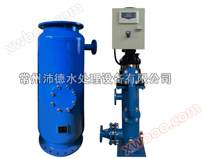
Structure of fully automatic shallow medium filter
The main components of the QLQ unit consist of a spherical tank, water distributor, collector, handhole, and support legs.
Spherical tank: can fully cooperate with the water distributor to evenly distribute water; Combined with the 55 water caps of the water collector, an inner loop flow is formed during backwashing without sand running.
Water distributor: enables unfiltered water to flow evenly through the packing layer even at high flow rates and maintain a flat water surface on the packing layer.
Water collector: A unique 55 mushroom shaped pressure differential compensation water collector ensures water pressure balance in all parts of the system during filtration, resulting in high filtration flow rate and efficiency; In the backwash state, an inner loop flow is formed, with high backwash efficiency and no sand running.
Hand hole: The filter has two hand holes, upper and lower, for easy installation and replacement of the water distributor and collector. The hand hole can be used for observation and feeding, and the hand hole can be used for emptying and maintenance.
Legs: Detachable legs facilitate transportation, reduce transportation costs, facilitate on-site installation, adjustable height, better adapt to uneven ground.
Working principle filtering states
When the system is in a filtered state, unfiltered water passes through the upper water distributor and, in conjunction with the spherical shell, reaches the packing layer inside the filter in a nearly laminar state. When water flows through the packing layer, impurities are trapped within the packing layer. The collector at the bottom of the filter evenly collects and flows out the filtered water. Advection filtration determines that the filter can still achieve good filtration effect at high flow rates.
Backwash status
As impurities accumulate in the packing layer, the head loss (i.e. pressure difference) will continue to increase. When the pressure difference reaches a certain set limit or the filtration time reaches the set value, the system will automatically switch to backwashing mode to clean the packing layer and remove accumulated impurities. For the system, regular backwashing is necessary to remove accumulated impurities. When the system enters the backwash state, the on/off position of the three-way valve is changed through PLC control (inlet closed, drain outlet open), and the filtered water from other filter tanks flows into the filter tank to be backwashed. Due to the pressure of the system being backwashed, the packing layer of the filtration unit is washed up by the impact of water flow, and impurities are discharged through the discharge port of the three-way valve. In the QLQ system, a specially designed water collector creates an inner loop flow in the packing layer during backwashing, where the packing materials rub against each other to maximize backwashing efficiency, reduce the required backwashing water, and prevent material loss during backwashing. When the backwash is completed, the valve returns to the filtering state, and the next filtering unit enters the backwash state. Generally, a system consists of multiple filter tanks (units) that are backwashed in sequence to ensure uninterrupted flow during backwashing.
Technical Parameter
1. Performance parameters
|
model |
QLQ48-1 |
QLQ48-2 |
QLQ48-3 |
QLQ48-4 |
QLQ48-5 |
QLQ48-6 |
|
Inlet and outlet main pipe diameter DN (mm) |
100 |
200 |
200 |
200 |
200 |
200 |
|
Discharge main pipe diameter DN (mm) |
80 |
100 |
100 |
100 |
100 |
100 |
|
Flow rate (T/H) |
15-50 |
30-100 |
45-150 |
60-200 |
75-250 |
90-300 |
|
Maximum working pressure (MPA) |
0.6(1.0) |
0.6(1.0) |
0.6(1.0) |
0.6(1.0) |
0.6(1.0) |
0.6(1.0) |
|
Filter area (M2) |
1.13 |
2.26 |
3.39 |
4.52 |
5.65 |
6.78 |
|
Total length (mm) |
1320 |
2640 |
3960 |
5280 |
6600 |
7920 |
|
Quartz sand (KG) |
860 |
1720 |
2580 |
3440 |
4300 |
5160 |
|
Discharge valve interface |
4”×3” |
4”×3” |
4”×3” |
4”×3” |
4”×3” |
4”×3” |
For larger traffic, more filtering units can be used in parallel.
2. Filter media and flow rate
|
Filtration |
Filter material 12-40CM |
Recommended traffic (T/H) |
Backwash flow rate (T/H) |
|
General filtering |
Quartz sand 1.0-2.0mm |
40-50 |
35-55 |
|
Fine filtration |
Quartz sand 0.5-1.0mm Bottom 1.0-2.0mm |
15-25 |
25-40 |
Other diameters of sand can be selected to achieve the desired filtration accuracy and pollution resistance.
3. Manufacturing material
|
Filter cylinder body |
Carbon steel (coated with epoxy asphalt paint) |
|
filter material |
Exquisite natural quartz sand |
|
Water distributor |
engineering plastic |
|
collector |
engineering plastic |
|
sealing ring |
Nitrile rubber |
Installation of fully automatic shallow medium filter
Installation sequence
1、Inspection of installation ground: The ground should be flat, with a flatness requirement of less than10mm/Per meter; Cement flooring requires a load-bearing capacity greater than3ton/square meter.
2、arrangeQLQUnit: WillQLQArrange the units according to the installation drawings.
3、Install the drain valve. (Groove type pipe joint connection)
4、Install the inlet and outlet drainage pipes. (During installation, pay attention to protecting the plastic drain valve to avoid damage, and if necessary, install a bracket to support the main pipe)
5、Install differential pressure switches, inlet and outlet pressure gauges, and exhaust valves, paying attention to the threaded connections to avoid misconnection.
6、giveQLQUnit wiring and piping.
Installation method


3、 Installation of hand hole cover
1. Place O-ring 5 into the O-ring groove of the handhole flange, cover handhole flange cover 4 (as shown in the figure, keep the handhole cover handle in a vertical position), and tighten all bolts 2 (including gasket 3) diagonally. (Installation of hand hole cover is the same as installation of hand hole cover)
4、 Installation of legs and leg covers

Step 3:QLQAssembly of system pipelines and circuits
QLQPipeline diagram
1Hydraulic pipeline connection
1. One three-way drain valve corresponds to one solenoid valve, and the on-site pipeline connections are shown by dashed lines a, b, c, d, e, and f.
2. The high-pressure interface of the differential pressure switch is connected to the inlet pipe interface through a φ 8 hose, and the low-pressure interface is connected to the outlet pipe interface through a φ hose, as shown by the dashed lines g1 and g2 in the figure.
IIPartial connection of the line
1、Each solenoid valve in the hydraulic control box corresponds to two wiring terminals in the electrical control box, for example, the live wire of solenoid valve 1 # is connected to the corresponding point 1, and the neutral wire is connected to point N as shown in the figure;
2、The connection of the differential pressure switch, power cord (220V AC), and ground wire is shown by the double dotted line in the figure.