-
E-mail
abc710599280@163.com
-
Phone
18255088613
-
Address
I Industrial Park, Datong Town, Tianchang City, Anhui Province
Product Categories
Tianchang Yuetong Instrument Co., Ltd
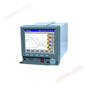
SWP-SSR series intelligent recorder
NegotiableUpdate on 08/18
- Model
- Nature of the Manufacturer
- Producers
- Product Category
- Place of Origin
Overview
1、 Introduction to SWP-SSR Series Paperless Recording Instruments SWP-SSR series intelligent paperless recording instruments are the latest generation of intelligent instruments developed by our company based on years of experience in digital instrument manufacturing, extensive research on advanced foreign products, and the characteristics of industrial field applications in China .....
Product Details
1、 Introduction to SWP-SSR series paperless recording instrument
|
The SWP-SSR series intelligent paperless recording instrument is the latest generation of intelligent instruments developed by our company based on years of experience in digital instrument manufacturing, extensive research on advanced foreign products, and the characteristics of industrial field applications in China.
|
|
The SWP-SSR series intelligent paperless recording instruments adopt multiple advanced technologies, greatly improving the stability and reliability of operation.
|
|
The appearance and structure of the SWP-SSR series intelligent paperless recording instrument have been greatly improved on the original basis, bringing greater convenience to users' installation and maintenance.
|
|
The SWP-SSR series intelligent paperless recording instrument, as a detection and control product in industrial process automation systems, has been widely used in industries such as national defense, steel, power, petrochemicals, machinery, pharmaceuticals, textiles, metallurgy, printing and dyeing.
|
|
The SWP-SSR intelligent paperless recorder incorporates the structural ideas of today's computers in its design: a new microprocessor with built-in flash memory is used in hardware, a large capacity data storage area is expanded, and a large screen LCD graphic display board is used as the display; The software introduces the framework of Chinese WINDOWS and adopts data compression technology. The quasi computerized structure highly reflects the superiority of microprocessor based instruments, successfully integrating a multifunctional instrument with flow/thermal energy accumulation that can achieve multi loop parameter monitoring, display multiple sets of numbers and graphic curves on the same screen/split screen, and contain large capacity data recording and storage space in a shell with a volume of 144 × 144 × 250 mm.
|
|
The SWP-SSR intelligent paperless recorder has made challenging reforms to traditional mechanical recorders in both human-machine operation and observation interfaces: guiding configuration operations with Chinese menus, displaying measurement processes and results with rich graphic and textual data, identifying the engineering meaning of screen content with clear Chinese information, replacing traditional recording pens and paper with large capacity semiconductor memory, overcoming various drawbacks and consumable costs of mechanical recorders, and giving people a simple and intuitive feeling of "intelligence".
|
|
2、 Characteristics of SWP-SSR series paperless recording instrument
|
|
1. Multi functional display screen:
|
|
Instrument panel configuration
|
|
2. Convenient operating interface:
|
|||||||||||||||||||||||||||||||||||||||||||||||||||||||||||||||||||||||||||||||||||||||||||||||||||||||||||||||||||||||||||||||||||||||||||||||||||||||||||||||||||||||||||||||
|
Quick Chinese menu prompts users to complete parameter settings step by step.
|
|||||||||||||||||||||||||||||||||||||||||||||||||||||||||||||||||||||||||||||||||||||||||||||||||||||||||||||||||||||||||||||||||||||||||||||||||||||||||||||||||||||||||||||||
|
Rich graphical display, providing parameter combinations that need to be displayed.
|
|||||||||||||||||||||||||||||||||||||||||||||||||||||||||||||||||||||||||||||||||||||||||||||||||||||||||||||||||||||||||||||||||||||||||||||||||||||||||||||||||||||||||||||||
|
The touch sensitive panel buttons facilitate users to perform various operations.
|
|||||||||||||||||||||||||||||||||||||||||||||||||||||||||||||||||||||||||||||||||||||||||||||||||||||||||||||||||||||||||||||||||||||||||||||||||||||||||||||||||||||||||||||||
★ Communication method:
★ Control output mode
|
|||||||||||||||||||||||||||||||||||||||||||||||||||||||||||||||||||||||||||||||||||||||||||||||||||||||||||||||||||||||||||||||||||||||||||||||||||||||||||||||||||||||||||||||
★ SCR - thyristor zero crossing trigger pulse output SSR - solid-state relay control output
★ Transmission output mode
|
Selection code
|
0
|
2
|
3
|
4
|
5
|
8
|
|
output method
|
No output
|
4~20mA
|
0~10mA
|
1~5V
|
0~5V
|
Special specifications
|
★ Input type
|
code
|
input type
|
Measurement range
|
code
|
input type
|
Measurement range
|
code
|
input type
|
Measurement range
|
|
01
|
B
|
400~1800 ℃
|
09
|
Pt100.1
|
-99.9~199.9℃
|
17
|
30~350Ω
|
-1999~99999 d
|
|
02
|
S
|
0 ~1600 ℃
|
10
|
Cu50
|
-50.0~150.0 ℃
|
18
|
Special specifications
|
User specific
|
|
03
|
K
|
0 ~1300 ℃
|
11
|
Cu100
|
-50.0~150.0 ℃
|
19
|
4-20 mA square root
|
-1999~99999 d
|
|
04
|
E
|
0 ~1000 ℃
|
12
|
4~20 mA
|
-1999~99999 d
|
20
|
0-10mA square root
|
-1999~99999 d
|
|
05
|
T
|
-200~400 ℃
|
13
|
0~10 mA
|
-1999~99999 d
|
21
|
1-5 V square root
|
-1999~99999 d
|
|
06
|
J
|
0 ~1200 ℃
|
14
|
1~5 V
|
-1999~99999 d
|
22
|
0-5V square root
|
-1999~99999 d
|
|
07
|
Wre
|
0 ~2300 ℃
|
15
|
0~5 V
|
-1999~99999 d
|
23
|
Fully switch input
|
Please refer to the table below for details
|
|
08
|
Pt100
|
-200~650 ℃
|
16
|
0~20 mA
|
-1999~99999 d
|
24
|
Frequency input
|
0-10KHz
|
★ Fully switchable input scale table
|
code
|
input type
|
code
|
input type
|
code
|
input type
|
code
|
input type
|
code
|
input type
|
|
01
|
B
|
05
|
T
|
09
|
Pt100.1
|
14
|
1~5 V
|
18
|
1-5 V square root
|
|
02
|
S
|
06
|
J
|
10
|
Cu50
|
15
|
0~5 V
|
19
|
0-5V square root
|
|
03
|
K
|
07
|
WRe
|
12
|
4~20 mA
|
16
|
4-20mA square meter
|
|
|
|
04
|
E
|
08
|
Pt100
|
13
|
0~10 mA
|
17
|
0-10mA square root
|
|
|
★ Alarm method:
|
code
|
N
|
H
|
L
|
G
|
A
|
|
alarm method
|
No alarm (can be omitted)
|
upper limit alarm
|
Lower limit alarm
|
Deviation internal alarm
|
Deviation outside alarm
|
★ Wiring diagram
★ Note: CH1-CH6 are input terminals for channels 1 to 6. (The above wiring diagram is based on a 6-channel fully switched input as an example)
★ Note 1: When the number of channels is 1-6, the instrument input scale can be fully switched; When there are more than 6 channels, the instrument scale cannot be switched. Please indicate the type of input scale. When the input signal is a thermal resistor, a maximum of 12 channels of input can be achieved, and when the input signal is a thermocouple or standard signal, a maximum of 16 channels of input can be achieved. If you want to have 4 outputs, only 4 input channels can be fully switched. If you have special requirements, please call us for consultation.
This instrument can carry up to 4 voltage/current outputs. I.e. OUT1:5A (+), 5B (-); OUT2:5D(+),5E(-); OUT3:6A(+),6B(-); OUT4:6D(+),6E(-)。Similar Product Recommend