-
E-mail
abc710599280@163.com
-
Phone
18255088613
-
Address
I Industrial Park, Datong Town, Tianchang City, Anhui Province
Product Categories
Tianchang Yuetong Instrument Co., Ltd
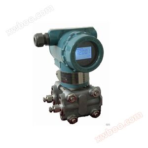
1151/3351DR type micro differential pressure transmitter
NegotiableUpdate on 08/18
- Model
- Nature of the Manufacturer
- Producers
- Product Category
- Place of Origin
Overview
The BT1151/3351DR micro differential pressure transmitter is used to measure small differential pressures such as furnace pressure, and then convert them into 4-20mA DC signal output. The intelligent differential pressure transmitter can also communicate with the HART controller for setting, monitoring, or on-site integration with the upper computer .....
Product Details
BT1151/3351DR typeMicro differential pressure transmitterUsed to measure small differential pressures such as furnace pressure, and then convert them into4~20mA DCSignal output. Intelligent micro differential pressure transmitter can also be used withHARThandheld controllerMutual communication is used to set up, monitor or form an on-site monitoring system with the upper computer. BT1151/3351DROn site adjustment typeIntelligent differential pressure transmitterThis is a new product developed by our company based on on-site requirements. It can be operated without a manual controller and can be adjusted and configured on-site through button pressing.
1. Performance Specifications
(Zero benchmark verification range, under reference conditions, filled with silicone oil,316 LStainless steel isolation membrane. )
◆Selection method
1. Performance Specifications
(Zero benchmark verification range, under reference conditions, filled with silicone oil,316 LStainless steel isolation membrane. )
|
1.1. Reference accuracy
2. Functional specifications |
|
2.2.2. Simulation, linear: range and zero point continuously adjustable |
|
SK1151/3351DR |
Micro differential pressure transmitter |
|||||||
|
|
code |
measurement rangeKPa |
||||||
|
2 |
0-0.125~1.5KPa |
|||||||
|
|
code |
output |
||||||
|
F |
4-20mA |
|||||||
|
|
code name |
structural material |
||||||
|
Flanges and fittings |
exhaust/drain valve |
Isolation Diaphragm |
Fill with liquid |
|||||
|
22 |
316stainless steel |
316stainless steel |
316stainless steel |
silicone oil |
||||
|
|
code name |
Great work pressureMPa |
||||||
|
A- |
1 |
|||||||
|
B- |
4(special6.9) |
|||||||
|
|
code |
option |
||||||
|
M1 |
0-100%Linear indicator table |
|||||||
|
M2 |
LED display table |
|||||||
|
M3 |
LCDdisplay table |
|||||||
|
B1 |
Pipe bending bracket |
|||||||
|
B2 |
Board mounted bending bracket |
|||||||
|
B3 |
Pipe mounted flat bracket |
|||||||
|
D1 |
The side relief valve is located at the upper part of the pressure chamber |
|||||||
|
D2 |
The side relief valve is located at the lower part of the pressure chamber |
|||||||
|
No note |
1/2NPTCone pipe threaded joint |
|||||||
|
C2 |
T-shaped threaded jointM20×1.5, with rear weldingФ14Spherical cone connector of pressure pipe |
|||||||
|
d |
Explosion proof typedⅡBT4 |
|||||||
|
i |
Intrinsically safe typeiaⅡCT6 |
|||||||
|
s |
Stainless steel three valve group |
|||||||
Similar Product Recommend