- Phone
-
Address
Jinze Industrial Park, Qingpu District, Shanghai
Product Categories
- Subsea pump model _ Subsea pump picture
- Deep well pump model _ Deep well pump picture
- Self priming pump model _ Self priming pump picture
- Centrifugal pump model _ Centrifugal pump picture
- High pressure pump model _ High pressure pump picture
- Diaphragm pump model _ Diaphragm pump picture
- Submersible pump model _ Submersible pump picture
Shanghai Boyu Pump Industry Co., Ltd

Machine tool submersible pump
NegotiableUpdate on 05/11
- Model
- Nature of the Manufacturer
- Producers
- Product Category
- Place of Origin
Overview
The BYQDY (N) A series machine tool submersible pump is used for conveying machine tool coolant, machine tool flushing fluid, lubricating oil, condensate water, industrial cleaning equipment, and other applications suitable for immersion pumps. BYQDYA is suitable for non corrosive liquids, while BYQDYN is suitable for mildly corrosive liquids. Specifically used in various industries such as machine tool matching, cleaning spray systems, condensing cooling systems, water treatment systems, etc.
Product Details
Machine tool submersible pump, machine tool cooling water submersible pump, machine tool submersible multi-stage pump
1、 Introduction to Machine Tool Submerged Pump
Used for conveying machine tool coolant, lubricating oil, condensate water, industrial cleaning equipment, and other applications suitable for immersion pumps. BYQDsubmerged pumpSuitable for non corrosive liquids, BYQD(N)submerged pumpSuitable for mildly corrosive liquids, specifically used in electric discharge machines, lathes, grinders, machining centers, cooling devices, industrial cleaning equipment, filtration systems, etc.
2、 MachineWorking principle of bed liquid submersible pump
machineBed liquid submersible pumpThe motor is located above and is directly connected to the pump shaft through a connecting block. The water inlet is located below, and it can directly absorb water when immersed in water. The water outlet is located above. The conveyed liquid enters the impeller from the bottom guide seat, and under the action of the high-speed rotating blades, both the kinetic energy and potential energy of the liquid increase. After the liquid enters the pressure chamber of the diffuser, its velocity decreases and kinetic energy is converted into potential energy. The liquid enters the second stage impeller through the guide vanes and obtains an increase in the second potential energy. Continuing in this cycle, the potential energy continues to increase, and the more impellers are connected in series, the higher the water pressure at the outlet. Finally, the pressurized water is discharged through the outlet section.

IIImachineSchematic diagram of the structure of the bed liquid submersible pump
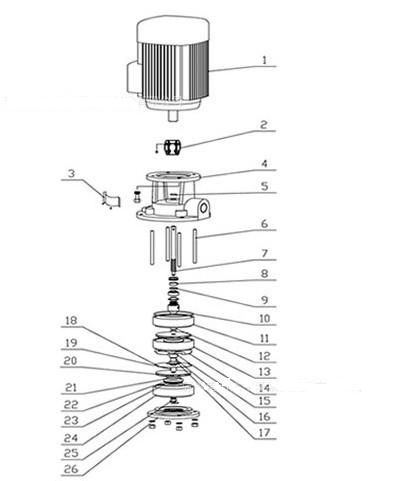
1. Three phase asynchronous motor 2, coupling 3, protective cover 4, inlet and outlet sections
5. Sealing ring 6, pull rod 7, pump shaft 8, static ring
9. Moving ring 10, sealing ring 11, guide housing 12, first stage sleeve
13. Guide shell 14, guide vane 15, shaft sleeve 16, alloy bearing
17. Bearing seat 18, guide vane partition 19, shaft sleeve 20, impeller
21. Water seal cover 22. Floating seal ring 23. Water seal seat 24. Flow guide shell
25. Lock nut 26. Bottom guide vane body seat
4machinePerformance parameter table of bed liquid submersible pump


5Ordering Notice for Submersible Pump
1. The depth of the water tank or container is used to select the structural form of the machine pump.
2. The name, temperature, density, concentration, viscosity, etc. of special liquids transported by machine tool pumps.
3. When there are special requirements for machine pump flow rate, machine pump head, machine pump power supply, etc., please indicate them in the remarks.
Similar Product Recommend


