-
E-mail
bjrkth@163.com
-
Phone
13911362653
-
Address
Industrial South District, Yangfang Town, Changping District, Beijing
Product Categories
- Temperature pressure linkage intelligent injection controller
- piston pump
- Electric six way valve head
- Pneumatic twelve way switching valve
- Electric twelve way valve
- ball valve
- Linear needle valve
- 1-4 Electric High Voltage Sequential Switching Valve
- 1-6 Electric High Voltage Sequential Switching Valve
- 1-10 Electric High Voltage Sequential Switching Valve
- Pneumatic Switching Valve Series
Beijing Ruike Tongheng Technology Development Co., Ltd

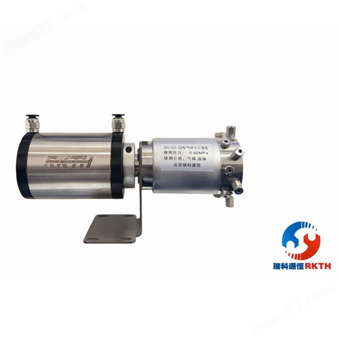
High temperature resistant 330 ℃ pneumatic extension rod ten way valve (axial)
NegotiableUpdate on 01/05
- Model
- Nature of the Manufacturer
- Producers
- Product Category
- Place of Origin
Overview
High temperature resistant 330 ℃ pneumatic extension rod ten way valve (axial) The operating pressure range of the ten way valve is 0-0.60 MPa. The operating pressure range of the $r $n cylinder is 0.2 to 0.60 MPa. The operating temperature range of the $r $n ten way valve is 0-330 ℃. The position of the $r $n extension rod can be adjusted arbitrarily
Product Details
1. Purpose:
High temperature resistant 330 ℃ pneumatic extension rod ten way valve (axial)Used for sampling, quantifying, gas path switching, and other instruments and equipment with similar requirements for gas sample volume.
2. Main technical parameters
1) Use pressure and temperature range:
The operating pressure range of the ten way valve is 0-0.60MPa
The operating temperature range of the ten way valve:0~330℃
The operating pressure range of the cylinder is 0.3 to 0.60MPa
The operating temperature range of the cylinder is 0-70 ℃
Switching times: Continuous operation at room temperature for more than 2 million times
2) Interface size:
Valve head interface: 1.6mm, 2mm, 3mm, 1/16 ', 1/8'
Cylinder interface: 1.6mm, 2mm, 3mm, 1/16 ', 1/8', tower type connector, quick twist connector, quick insert connector
3) Media used: gas, liquid
3. Outline and installation dimension diagram

4. Working principle of switching valve
1. Working principle of cylinder

2. Working principle of switching valve

5. Repeatability and cleanliness testing (see the diagram below)
High temperature resistant 330 ℃ pneumatic extension rod ten way valve (axial)The cleanliness detection spectrum was obtained using the original Beijing Analytical Instrument Factory's sp-3420 gas chromatography, FID detector, range 12 (i.e. 10-12), 8M0.32 test column, column sampler temperature 200 ℃, column box temperature 200 ℃, detector temperature 250 ℃, as shown in Figure 2
The repeatability detection spectrum of the valve, column box at 100 ℃, injector at 150 ℃, detector at 150 ℃, with a range of 12 (i.e. 10-12), as shown in Figure 3

6. Usage and maintenance
a. Oil stains, dust, and all mechanical impurities should be prevented from entering the valve body
b. Oil stains, dust, and all mechanical impurities should be prevented from entering the cylinder
c. There should be no leakage at the connection between the inlet and outlet pipes and the valve body
d. There should be no looseness or sliding at the connection between the valve head and the cylinder to prevent improper switching
7. Common problems and solutions during the installation process of switching valves