-
E-mail
wangguijiang@bjguancheng.com
-
Phone
18513000801
-
Address
Room 104, Building C, Hongxianghong Enterprise Incubation Base, Beiqijia Town, Changping District, Beijing
Product Categories
- RF level switch
- Pulse radar level gauge/pulse radar liquid level gauge
- Guided wave radar level gauge/guided wave radar liquid level gauge
- Resistance rotary level switch
- Intelligent pressure switch
- Boiler drum level gauge
- Differential pressure transmitter
- Pressure transmitter/static pressure level gauge
- RF admittance level meter
- Fork level switch
- Input type static pressure level gauge
- Thermistor temperature sensor/transmitter/switch
- Deep well level gauge/deep well pressure gauge
- RF liquid level controller/static pressure liquid level controller
Beijing Guancheng Measurement Technology Co., Ltd

GCD300 series RF level switch
NegotiableUpdate on 05/16
- Model
- Nature of the Manufacturer
- Producers
- Product Category
- Place of Origin
Overview
GCD300 series RF level switch
Product Details

Product Features
The GCD300 series capacitive level switch adopts advanced capacitive technology, which has solved the problem of RF admittance switches
Defects that can eliminate the influence of conductive hanging materials. The instrument operates reliably, and all technical indicators meet the standards of similar international products
Horizontal, widely applicable for liquid, slurry, dust, material level, and ultra-high temperature material alarm and control. In addition,
The product has added on-site working status indication, which is a highly cost-effective and stable level switch.
application area
GCD300 is a limit level sensor with partially insulated capacitive electrodes used for measuring limit levels.
Can be used in all fields of industrial processes, mainly in the field of solid materials. But limit switches can also be used for liquids,
Typical applications include overflow and dry motion protection. The principle of capacitance measurement does not impose too many requirements on installation, therefore
Can equip more application scenarios.
Working principle
Measure the electrode, medium, and container to form a capacitor. The capacitance of a capacitor is mainly influenced by three factors.
Functional principle - Board capacitor electrode:
1. Distance from electrode surface
2. Electrode surface size
3. Dielectric type between electrodes
That is, the electrode and container wall are capacitor plates, and the medium is electrolyte. Due to the higher relative humidity of the medium compared to air
The influence of dielectric constant increases the capacitance of a capacitor as the electrode coverage increases, and the change in capacitance is influenced by electronic insertion
Convert the item into a switch command.
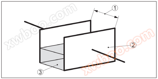
External dimensions
The GCD300 series consists of the following components:
·Instrument cover
·Shell with electronic components
·Process connection and electrodes

1. Shell cover;2. Shell with electronic components; 3 process connections; 4. Protecting electrodes; 5. Measuring electrode
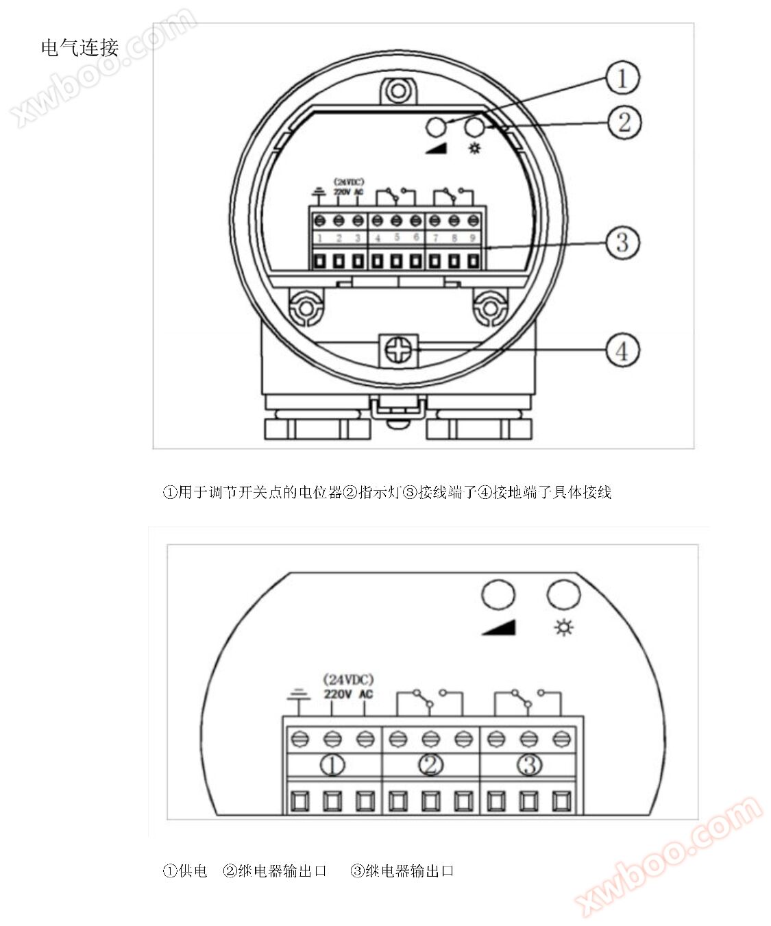
power supply
The GCD300 series is an integrated instrument that does not require the connection of additional computing instruments. Integrated electronic components
Analyze and calculate the level signal, and provide switch signals. This switch signal can directly control the devices connected later
(For example: alarm system, DCS or pump, etc.). The power supply voltage of GCD300 series is shown in the "Selection Table"
sensitivity
The measuring electrode can adapt to the dielectric constant of the medium through electronic components. It can be measured when the electrode is covered or measured
Adjust
Provide a switch signal when the electrode is not covered. The following display and adjustment components can be found on electronic components:
Clockwise adjustment increases sensitivity, counterclockwise adjustment decreases sensitivity. When switched to red green conversion, the sensitivity is highest.
·LED display light is used to show the switch status (green/red)
·Potentiometer for adjusting switch points
Wet environment
Apply the recommended connecting cable and tighten the cable entry. To prevent moisture, it is necessary to connect the cable in front of the cable entrance
Down. In this way, rainwater and condensate can drip down along the hanging cables. This corresponds to outdoor installation or
It is important to install in damp places (such as cleaning with water, heating or cooling).

Measures to prevent moisture infiltration
If condensation appears on the container lid, the flowing liquid will form a bridge, leading to circuit failure. Therefore, please
Use a shielded tube or a longer insulated tube. Its length depends on the condensation capacity and the flow of the medium.
Installation position
If the instrument is installed in the filling flow, it will cause measurement errors. Therefore, please install the instrument without being affected
The location affected by interference from filling holes.

If there is a need to install a short tube, the protective electrode should be extended out of the short tube to avoid instrument errors caused by the accumulation of aggregates in the short tube
The action in the solid material bin will form a conical pile, which will change the switch point. Therefore, please pay attention to this during the installation process
Point. Therefore, it is recommended to choose a measuring electrode that can measure the average value of the conical material pile at the installation position.
It must be installed according to the layout of the filling and emptying ports in the container. To compensate for the conical solid material in cylindrical containers
The measurement error caused must be installed with the instrument at a distance of d/6 from the container wall

Order Selection Table


