-
E-mail
ethan@lab-tester.com
-
Phone
13926824844
-
Address
Room 601, Building 2, R&D Building, Lihe Zijing Science and Technology Innovation Center, No. 55 Qinghu East Road, Qingxi Town, Dongguan City, Guangdong Province
Product Categories
Dongguan Hongtu Instrument Co., Ltd
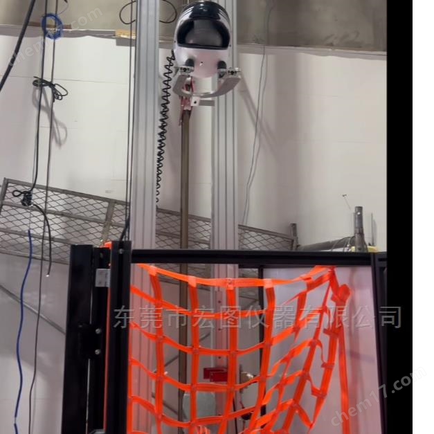


ECE R22.06 Helmet Absorption Collision Energy Testing Machine
NegotiableUpdate on 01/05
- Model
- Nature of the Manufacturer
- Producers
- Product Category
- Place of Origin
Overview
The ECE R22.06 helmet energy absorption test machine is used to evaluate the impact resistance performance of helmets This machine adopts HOTOTECH's self-developed upper computer control system, which automatically lifts the fixture to the predetermined height, displays the height in real time, and displays the acceleration peak value, test curve, impact speed, HIC value, action time, impact energy, etc. in real time on the operation interface.
Product Details
HT-6011-D ECE R22.06 Helmet Absorption Collision Energy Testing Machine
Applicable standards:
According to the requirements of ECE R22.06, GB 811-2022, GB24429-2009, and EN 1078:2023 standards
Scope of application:
ECE R22.06 Helmet Absorption Collision Energy Testing MachineIt is used to evaluate the impact resistance of helmets This machine adopts HOTOTECH's self-developed upper computer control system, which automatically lifts the fixture to the predetermined height, displays the height in real time, and displays the acceleration peak value, test curve, impact speed, HIC value, action time, impact energy, etc. in real time on the operation interface.
Features:
1. Total height of the machine: approximately 6.0m
2. Sensor: Three channel wireless angle sensor, range: 0-2000g
4. Special computer control software should be equipped to control the testing actions
5.1 Real time display of peak acceleration and real-time drawing of acceleration curve
5.2 The software can display HIC values
5.3 Acceleration curve can be viewed by zooming at any point
5.4 The software can input the action time of any acceleration point and participate in the result evaluation
5.5 The impact height can be set arbitrarily and displayed in real-time
5.6 Real time display of impact speed by software and reflection in reports
5.7 Real time calculation and display of friction coefficient using software
5.8 The software has a separate calibration channel, which can be used to calibrate acceleration sensors, velocity sensors, displacement, communication frequencies, sampling frequencies, etc
Perform calibration and modification
5.9. Automatically calculate the acceleration action time and automatically evaluate it
5.10. The software has multi standard compatibility and can be customized to add evaluation criteria and conditions according to user needs
5.11. Automatically display the maximum acceleration value;
5.12. The software supports data storage, historical data query, data export/printing, etc
5.13 Testing software: The device reserves ports for other testing standards to facilitate the use of other testing standards for future equipment expansion. There is no need to upgrade the device, only the head mold needs to be replaced.
Technical specifications:
1. Use wireless angular velocity sensors and linear impact sensors
2. Impact speed (speed and test height can be set in the software)
7.5+0.15m/s is suitable for flat anvil and curbstone anvil
The speed of point S is 6.0+0.15m/s
8.2 ± 0.15m/s for linear high energy, using a flat anvil
6.0 ± 0.15m/s for linear low energy, using flat anvil and curbstone anvil
3. Impact height: maximum 3m, adjustable height.
4. Types of test anvil used: flat anvil, triangular anvil, inclined anvil
4.1 Flat anvil diameter: 130 ± 3mm
4.2 Triangular anvil: Two inclined surfaces form an angle of 105 ± 5 º, with a single-sided angle of 52 ± 2.5 º. The intersecting radius of the impact edge is 15mm ± 0.5mm, with a height of 50mm and a length of 125mm
4.3. Slanted anvil: The anvil seat (A) is made of a solid steel cylinder with a diameter (d) of 130 millimeters. Then, use a 45 ° angle (a) to cut the cylinder, and the angle (a) of the anvil should be defined from the horizontal plane. The height of the base (h) should be 30 millimeters ± 2 millimeters.
Impact speed: 8.0m/s+0.15m/s
4.3.1. Impact point location: 45 ° to the right of the front outer side, 180 ° to the rear, 270 ° to the left outer side, 0 ° to the front, 135 ° to the right of the rear outer side, etc
The collision location diagram is as follows:

5. Angular acceleration: 1000rad/s2Up to 25000 rad/s2
6. Angular velocity: 5rad/s to 70rad/s
7. The equipment is equipped with dedicated computer control software to control the testing actions
7.1 Real time display of peak acceleration and real-time drawing of acceleration curve
7.2 The software can display HIC values
7.3 Acceleration curve can be viewed by zooming at any point
7.4 The software can input the action time of any acceleration point and participate in the result evaluation
7.5 allows for arbitrary setting of impact height and real-time display of impact height
7.6 Real time display of impact speed by software and reflection in reports
7.7 Real time calculation and display of friction coefficient using software
7.8 The software has a separate calibration channel, which can be used to calibrate acceleration sensors, velocity sensors, displacement, communication frequencies, sampling frequencies, etc
Perform calibration and modification
7.9. Automatically calculate the acceleration action time and automatically evaluate it
7.10. The software has multi standard compatibility and can customize evaluation criteria and conditions according to user needs
7.11. Automatically display the maximum acceleration value;
7.12. The software supports data storage, historical data query, data export/printing, etc
7.13. Testing software: The device reserves ports for other testing standards to facilitate the use of other testing standards for future equipment expansion. There is no need to upgrade the device, only the head mold needs to be replaced.
7.14. It has multiple protection functions: adjustable upper and lower limit protection, emergency stop protection, etc
Similar Product Recommend


