- Phone
-
Address
Building 6, Optics Valley Electromechanical Industrial Park, No. 84 Gaoxin 5th Road, Donghu New Technology Development Zone, Wuhan City, Hubei Province
Product Categories
Wuhan Ultra High Voltage Power Technology Co., Ltd
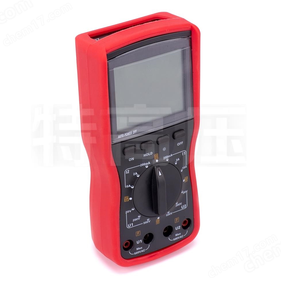
Digital dual clamp phase voltmeter
NegotiableUpdate on 05/06
- Model
- Nature of the Manufacturer
- Producers
- Product Category
- Place of Origin
Overview
The SMG2000 series digital dual clamp phase volt ampere meter features a large LCD display screen with words up to 40mm in height. It also has a white screen backlight, making the display clear at a glance and showcasing its exquisite and luxurious appearance.
Product Details
The SMG2000 series digital dual clamp phase voltmeter is another multifunctional instrument specially developed by our company for on-site testing. It has the characteristics of high precision, high stability, low power consumption, and easy use. It is possible to directly measure AC voltage and AC current without an open circuit in the tested circuit, measure the phase between two voltages, two currents, and voltage current, and indirectly measure the power factor and power of the circuit. It can also distinguish the three-phase phase sequence, transformer wiring group, inductive and capacitive circuits, test the secondary circuit and bus differential protection system, read out the phase relationship between the CT of each differential protection group, check whether the wiring of the electricity meter is correct, and repair the line equipment.
The SMG2000 series digital dual clamp phase volt ampere meter features a large LCD display screen with words up to 40mm in height. It also has a white screen backlight, making the display clear at a glance and showcasing its exquisite and luxurious appearance.
Product nickname: Phase meter, dual clamp phase meter, dual clamp phase volt ampere meter, clamp phase meter, clamp phase volt ampere meter, digital dual clamp phase meter, digital dual clamp phase meter, low-voltage volt ampere phase detection meter, handheld digital dual clamp phase volt ampere meter, dual clamp digital phase meter, dual clamp digital phase meter, dual clamp volt ampere phase meter, dual clamp volt ampere phase meter, digital dual clamp phase meter, phase volt ampere meter
Digital dual clamp phase voltmeterparameter
Benchmark conditions and working conditions
| impact quantity | Benchmark conditions | working conditions |
| ambient temperature | 23℃±1℃ | -10℃~40℃ |
| ambient humidity | 40%~60% | <80% |
| signal waveform | Sine wave β=0.05 | Sine wave β=0.05 |
| signal frequency | 50Hz±1Hz | 45Hz~65Hz |
| Instrument working voltage | 9V±0.1V | 9V±1V |
| Voltage amplitude during phase measurement | 100V±20V | 30V~500V |
| Current amplitude during phase measurement | 1A±0.2A | 10mA~20.00A |
| External electric and magnetic fields | should be avoided | |
| Position of the tested wire | The tested wire is located at the approximate geometric center of the clamp | |
General specifications
| function | Direct testing of phase, AC current, AC voltage, AC leakage current, and phase sequence; Transformer group, inductive and capacitive circuit discrimination; Power factor and indirect power testing |
| power supply | DC9V alkaline dry battery (1.5V LR6 × 6) |
| operating current | Turn on the backlight for about 35mA, and the battery will work continuously for about 15 hours |
| Turn off the backlight, the instrument consumes about 5mA, and the battery works continuously for about 100 hours | |
| display mode | LCD display, white screen backlight function, suitable for dim places |
| LCD size | 70mm×62mm ; 显示域: 64mm×54mm |
| Instrument size | Length, Width, and Thickness: 196mm × 92mm × 54mm |
| sampling rate | About 3 times per second |
| range | AC voltage: 0-20V/200V/500V |
| AC current: 0-20mA/2A/20A | |
| Phase: 0-360 ° | |
| The amplitude range of the measured signal when measuring phase | When measuring U1-U2 phase: 30V~500V |
| When measuring I1-I2 phase: 10mA~10.00A | |
| When measuring U1-I2 or I1-U2 phase: 10V~500V, 10mA~10.00A | |
| data retention | Press the HOLD key to hold the data during testing, and the "DH" symbol will be displayed |
| Auto Shutdown | After about 15 minutes of startup, the instrument panel automatically shuts down to reduce battery consumption |
| Voltage detection | When the battery voltage is below 7.8V~8V, replace the battery |
| Instrument quality | The host weighs about 1140g (with battery), the meter clamp weighs about 170g × 2, and the test line weighs about 250g |
| Test line length | 1.5m |
| Current clamp wire length | 2m |
| Operating Temperature | -10℃~40℃; Below 80% Rh |
| Storage temperature and humidity | -10℃~60℃; Below 70% Rh |
| input impedance | The input impedance of each voltage level for testing is 1m Ω |
| When measuring the phase of U1U2, the voltage input impedance is 40k Ω | |
| pressure resistance | The instrument circuit and the casing can withstand a sine wave AC voltage of 1000V/50Hz for 1 minute; Test on the ability to withstand a sinusoidal AC voltage of 500V/50Hz between two voltage input terminals for 1 minute |
| insulation | Between the instrument circuit and the casing, and between the two voltage input terminals, ≥ 10m Ω |
| structure | Double insulation |
Basic error and performance indicators under benchmark conditions
| voltage | 20V | 0.01V | ± (0.5% range) ° |
| 200V | 0.1V | ||
| 500V | 1V | ||
| current | 200mA | 0.1mA | ± (0.5% range) ° |
| 2A | 1mA | ||
| 20A | 10mA | ||
| phase | 0~360° | 1° | ±1° |
Note:
1. The appearance of the product is subject to the actual product. Technical parameters and models are subject to change without prior notice. If there is any act of theft or copying, legal responsibility will be pursued.
2. For more information on ultra-high voltage products, please enter the product center.
Product features
1. Distinguish the three-phase phase sequence, transformer wiring group, inductive and capacitive circuits, test the secondary circuit and bus differential protection system, and read out the phase relationship between the CTs of each differential protection group.
2Digital dual clamp phase voltmeterIt has the characteristics of high precision, high stability, low power consumption, and easy use.


Product Video Product Atlas
Product Attachment Diagram

host

test line

battery

current clamp

Aluminum alloy chassis
Product detail images

complete set

Front panel of the main unit

Side of the host

switch

Select knob

socket

panel

outer box
Similar Product Recommend


