- Phone
-
Address
L19-005, Building L19, South China International Leather and Leather Raw Material Logistics Zone (Phase I), No.1 South China Avenue, Hehua Community, Pinghu Street, Longgang District, Shenzhen City
Product Categories
Shenzhen Yimai Optoelectronics Co., Ltd


Confocal sensor
NegotiableUpdate on 05/07
- Model
- Nature of the Manufacturer
- Producers
- Product Category
- Place of Origin
Overview
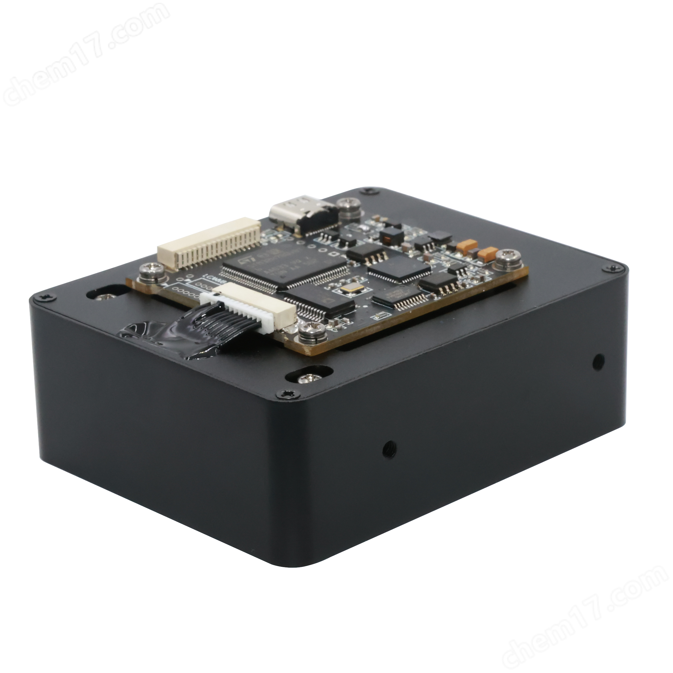
The confocal sensor is driven by high-performance ARM and FPGA dual controllers, with strict driving timing and noise control circuit design, resulting in low noise output images. It uses a 16 bit professional CCD processor, with TTL interface and USB 2.0 interface. USB adopts virtual serial port technology, no need to install driver programs, and is as easy to use as serial ports. The transmission speed can reach up to 12Mbps, and the frame rate can reach more than 200 frames per second. It has TTL interface, which is convenient for interconnection and control with other devices, and supports external trigger input and output.
Product Details
Confocal sensorThe main characteristics are:
1. ARM+FPGA driver, 16 bit CDS differential sampling, high dynamic range;
2. USB Virtual Serial Port (VCP), serial programming, TTL interface, support UART, hard touch, adjustable analog voltage output, Trigger output, hernia light control, etc;
3. Synchronize charge integration for all pixels;
4. From ultraviolet to near-infrared region (spectral response range: 200-1000nm);
5. Anti interference circuit design, suitable for industrial complex environments with strong interference;
6. Support software and hardware customization, support secondary development, provide QT C++, LabVIEW, Python SDK Demo source code and communication protocol;
7. System support: Windows, Linux, MAC, Android;
Usage: Spectral analysis, UV spectroscopy, near-infrared spectroscopy, image recognition, remote sensing detection, industrial measurement.
Order model:
LCAMV8-S11639
LCAMV8-S11638
LCAMV8-S13496
LCAMV8-S15796
LCAMV8-ILX511
LCAMV8-ILX511B
LCAMV8-ILX554
LCAMV8-TCD1304
LCAMV8 (single drive board)
Technical parameters:
model |
LCAMV8-S11639 |
LCAMV8-S11638 |
LCAMV8-S13496 |
Chip type |
Hamamatsu S11639-01 |
Hamamatsu S11638 |
Hamamatsu S13496 |
interface |
USB-Type C,TTL, Support external triggering and synchronous signal input and output |
||
effective pixels |
2048 x 1 |
4096 x 1 |
|
pixel size |
14 x 200 μm |
14 x 42 μm |
7 x 200 μm |
sensitivity |
1300 V/(lx·s) |
160 V/(lx·s) |
650 V/(lx·s) |
signal-to-noise ratio |
370:1 |
200:1 |
370:1 |
Spectral response range |
200nm~1000nm |
||
Detection surface size |
28.672mm x 200 um |
28.672mm x 42 um |
28.672mm x 200um um |
TTL serial port baud rate |
115200/384000/921600 switchable |
||
TTL level |
Input 3-5V, output 5V |
||
CCD clock |
4.8MHz |
||
TTL analog output |
0-5V,0.12mV,12bit 高精度DAC |
||
Maximum frame rate |
USB>180 fps, TTL serial port>30 fps (@ 921600 baud rate) |
USB trigger>100 fps, TTL serial port>15 fps fps (@ 921600 baud rate) |
|
exposure time |
20us ~65s, |
||
average frequency |
1-255 |
||
power consumption |
1W |
||
power supply |
5V |
||
size |
Motherboard: 65 x 40 mm, Sensor board: 50 x 15 mm |
||
Spectral response diagram |
|
||

model |
LCAMV8-511 |
LCAMV8-511B |
LCAMV8-554 |
Chip type |
SONY ILX511 |
SONY ILX511B |
SONY ILX554 |
interface |
USB-Type C,TTL, Support external triggering and synchronous signal input and output |
||
effective pixels |
2048 x 1 |
||
pixel size |
14 x 200 μm |
14 x 56 μm |
|
sensitivity |
200 V/(lx·s) |
240 V/(lx·s) |
|
Spectral response range |
380nm~1000nm |
||
Detection surface size |
28.672mm x 200 um with 100% fill factor |
28.672mm x 56 um with 100% fill factor |
|
TTL serial port baud rate |
115200/384000/921600 switchable |
||
TTL level |
Input 3-5V, output 5V |
||
TTL analog output |
0-5V, 1mV resolution |
||
Maximum frame rate |
USB soft trigger: 200 fps, TTL serial port: 20 fps (@ 921600 baud rate) |
||
exposure time |
1ms ~65s |
||
average frequency |
1-255 |
||
power consumption |
0.85W |
||
power supply |
5V |
||
size |
Motherboard: 65 x 40 mm, Sensor board: 50 x 15 mm |
||
Spectral response diagram |
|
|
|


model |
LCAMV8-S15796-2048-20 |
||
Chip type |
Hamamatsu S15796-2048-20 |
||
interface |
USB-Type C,TTL, Support external triggering and synchronous signal input and output |
||
effective pixels |
2048 x 1 |
||
pixel size |
7 x 200 μm |
||
sensitivity |
650V/(lx·s) |
||
signal-to-noise ratio |
500:1 |
||
Spectral response range |
200nm~1000nm |
||
Detection surface size |
14.336mm x 200 um |
||
TTL serial port baud rate |
115200/384000/921600 switchable |
||
TTL level |
Input 3-5V, output 5V |
||
CCD clock |
4.8MHz |
||
TTL analog output |
0-5V,0.12mV,12bit 高精度DAC |
||
Maximum frame rate |
USB>180 fps, TTL serial port>30 fps (@ 921600 baud rate) |
||
exposure time |
20us ~65s, |
||
average frequency |
1-255 |
||
power consumption |
1W |
||
power supply |
5 ± 0.5V, maximum not exceeding 5.5V |
||
size |
Motherboard: 65 x 40 mm, Sensor board: 50 x 15 mm |
||
Spectral response diagram |
|
||

model |
LCAMV8-TCD1304 |
Chip model |
TOSHIBA TCD1304DG |
Chip type |
CCD |
effective pixels |
3648 x 1 |
pixel size |
8 x 200 μm |
Detection surface size |
29.1mm x 200 um with 100% fill factor |
sensitivity |
160V/s•lx @ daylight fluorescent lamp |
interface |
USB-Type C,TTL |
TTL serial port baud rate |
115200/384000/921600 switchable |
TTL level |
Input 3-5V, output 5V |
Maximum frame rate |
USB: 80 fps, TTL serial port: 15 fps (@ 921600 baud rate) |
exposure time |
10us ~65s, Adjustment accuracy 1us |
average frequency |
1-255 |
power consumption |
1W |
power supply voltage |
3-5.5V |
Analog output: |
0-5V, 0.12mV, 12bit DAC |
size |
Motherboard: 65 x 40 mm, Sensor board: 50 x 15 mm |
analog output |
0-5V, Accuracy 1mV |
Spectral response diagram |
|


pin |
name |
function |
1 Pin |
VUSB |
5V power input |
2 Pin |
VGND |
5V power input |
3 Pin |
USB DP |
USB Data D+ |
4 Pin |
USB DM |
USB Data D- |
5-8Pin |
Rev |
retain |
9 Pin |
UART RX |
Serial data interface port (3.3V) |
10Pin |
UART TX |
Serial data transmission port (3.3V) |
11Pin |
Trigger In1 |
Single external trigger input (3.3V) |
12Pin |
Trigger In2 |
Continuous external trigger input (3.3V) |
13Pin |
Sync |
Synchronous signal output, 5V level |
14Pin |
Trigger Out2 |
Programmable output, 5V level |
15Pin |
Analog Out |
0-5V, Programmable voltage output |
16Pin |
GND |
GND |
LTriggerIn1: Start capturing the current image at the rising edge of the pulse, and automatically output the image upon completion. The exposure time is controlled by the MCU, with a default high level and a falling edge trigger.
LTriggerIn2: External trigger pin, 3.3V level, maximum 5V, PWM pulse input mode, high-level duration is the integration time of CCD, low-level duration is the acquisition and transmission time, low-level duration needs to last for a minimum of 4ms, high-level duration needs to last for a minimum of 10us
LSync: Output the synchronous trigger signal of the sensor, positive pulse output, rising edge image sensor electronic shutter opens, sensor begins integration, high-level duration is the exposure time, can be directly connected to the trig pin of the xenon lamp lTriggerOut2: Programmable output, provides a control interface, and users can control the output status of this port through software.
LAnalogOut: Programmable analog voltage output interface, with a voltage range of 0-5V and a resolution of 1.2mV.
Software usage: After plugging in the USB cable, open the Device Manager and find the corresponding port number (for systems below Win10, drivers need to be installed, please refer to the product manual for download addresses)

Open the software, select the corresponding port number, click Open to open the device and control the software interface (provide QT C++project source code):

Dimensional drawing: