- Phone
-
Address
North of West Wei 1st Road, Jingshi Road, Tianchang City, Anhui Province
Product Categories
Anhui Zhongchao Electric Co., Ltd

ZCWJ-100-1211 Vortex Flow Meter
NegotiableUpdate on 05/24
- Model
- Nature of the Manufacturer
- Producers
- Product Category
- Place of Origin
Overview
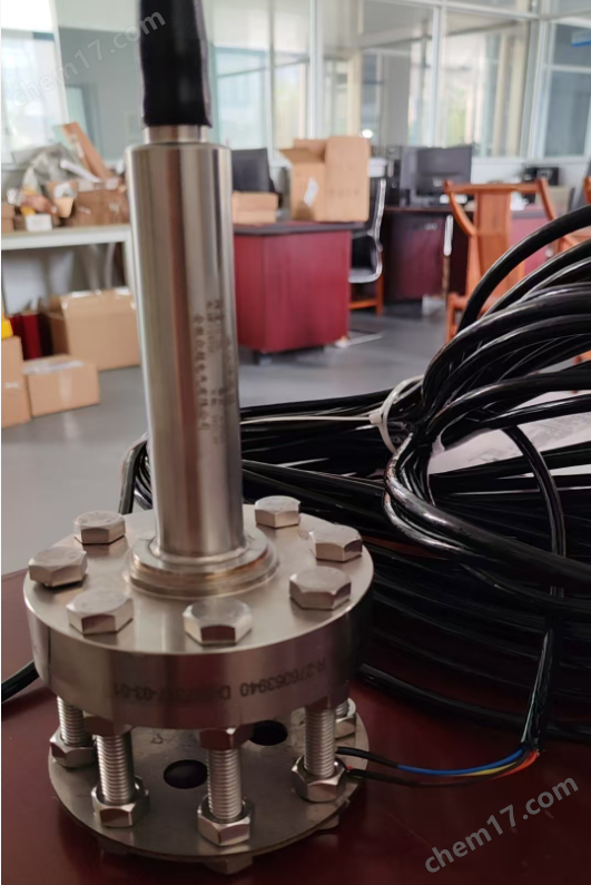
The ZCWJ-100-1211 vortex flowmeter series is manufactured using the Karman vortex principle and has the advantages of high measurement accuracy, wide range ratio, low power consumption, simple and firm structure, easy installation, simple operation, low pressure loss, and no on-site debugging. The integrated design flange installation method uses superheated water as the medium, with a temperature of 120 ℃ and a pressure of 0.3MPa. The pipeline diameter is DN100 and the range is 0-50m; /The wiring method for temperature and voltage compensation with H-band is a two-wire system. The power supply voltage is 24VDC, and the output 4-20mA signal has an accuracy level of 0.5,
Product Details
1vortex flow meterZCWJ-100-1211
ZCWJ-100-1211vortex flow meterMade using the Karman vortex street principle, it has the advantages of high measurement accuracy, wide range ratio, low power consumption, simple and sturdy structure, easy installation, simple operation, low pressure loss, and no on-site debugging. It is currently an ideal gas measuring instrument.
1. Large screen clear LCD display: Data display is clear and fast, ensuring fast data reading. Comfortable buttons, easy to operate.
2. Integrated header: Accurate precision, stable performance, SMT surface mount technology is used inside the header, with high assembly density. The volume and weight of surface mount components are only about 1/10 of traditional plug-in components, reducing the volume of electronic products by 40%~60% and weight by 60%~80%. High reliability and strong seismic resistance. The defect rate of solder joints is low. Good high-frequency characteristics, reducing electromagnetic and radio frequency interference. Easy to implement automation and improve production efficiency.
3. * * Circuit board: Imported * * circuit board with strong anti-interference ability ensures measurement accuracy and durability.
4. High precision probe, using 304 stainless steel encapsulated piezoelectric chip to form vortex sensor, with stable signal. 304 stainless steel has strong corrosion resistance and good intergranular corrosion resistance. It also has good corrosion resistance to alkaline solutions and most organic and inorganic acids.
5. Long life lithium battery: equipped with 3.6V high-energy polymer lithium battery, it has high storage energy density, a service life of more than 2 years, high power bearing capacity, light weight, strong high and low temperature adaptability, green environmental protection and other advantages.
IIvortex flow meterZCWJ-100-1211 Main Technical Parameters
Measurement medium: gas
Application scenarios: All sites where gases are produced and used
*High medium temperature: 200 ℃
*High working pressure: 1.6MPa~25MPa
Accuracy: Level 1.0, Level 1.5
Explosion proof grade: ExdIIBT4
Protection level: Regular IP65, Submersible IP68
Environmental temperature: -40 ℃ to+55 ℃
Body material: 1Cr18Ni9Ti (other material agreements)
Allowable vibration acceleration: piezoelectric 0.2g, capacitive 1.0-2.0g
3、 Gasvortex flow meterZCWJ-100-1211 Connection Method and Specifications
Internal/external thread connection type: DN15~DN50
Clamp type: DN15-DN50;
Card clamping type, flange connection type: DN15~DN30
Simple/Ball Valve Insertion Type: DN200~DN2000
4vortex flow meterZCWJ-100-1211 selection suggestion
vortex flow meterThe structural characteristics are classified as ordinary type and integrated temperature and pressure compensationvortex flow meterTwo types.
temperature and pressureCompensation integrated gasvortex flow meterIntegrating temperature sensors, pressure sensors, and display devices, it has intelligent temperature and pressure compensation functions, comes with a 3.6V high-energy battery or 24VDC power supply (usually used when pulse signal output, two-wire 4-20mADC output, or RS485 communication is required), and displays the medium temperature (℃), working pressure (MPa), instantaneous standard volume flow rate (Nm3/h), and cumulative standard volume flow rate (Nm3) on the local LCD display.
Ordinary gasvortex flow meterIt refers to the situation where only the volumetric flow rate of the working condition is required to be measured (which we define as a common type, usually suitable for situations where the medium temperature and working pressure are basically constant), whether it is an integrated or a split type, it does not have intelligent temperature and pressure compensation functions, nor does it have the configuration of temperature sensors and pressure sensors. At this time, only instantaneous volumetric flow rate (m3/h) and cumulative volumetric flow rate (m3) of the working condition are displayed.

Flow meter caliber corresponds to flow range:

Note: The diameters (200) - (1000) in the table are insertable.
Selection Guide

5、 Structural form and installation
Instrument appearance and dimensions

VIInstallation requirements and precautions for ZCWJ-100-1211 flowmeter
1. Requirements for the environment
The flow meter must be installed indoors and should have moisture-proof and sun protection measures when installed outdoors.
Flow meters should be avoided from being installed in places with strong electromagnetic field interference, small space, and inconvenient maintenance.
Flow meters should be avoided from being installed in places with high temperatures, equipment thermal radiation, or corrosive gases. If installation is necessary
At this time, insulation and ventilation measures must be taken.
2. Requirements for straight pipe sections
In order to ensure accurate measurement, there must be a sufficiently long straight pipe section upstream of the flowmeter, and the upstream flow distribution should be as undisturbed as possible. If there are control and throttling devices installed downstream. The length of the straight pipe section is expressed as a multiple of the inner diameter D of the pipeline. The requirements for straight pipe sections with smaller upstream and downstream diameters are as follows:
Upstream: 10D (10 times caliber)
Downstream: 5D (5x caliber)
If there are bends, reduced diameter, expanded diameter, valves, etc. upstream of the flowmeter, a longer straight pipe section is required, as shown in Figure 6.
0.98D≤ DN ≤1.05D
In the formula: D is the inner diameter of the flowmeter
DN pipe inner diameter
The piping should be concentric with the flow meter, and the coaxial deviation should not exceed 0.05 DN.
4. Treatment of pipeline vibration
Flow meters should be avoided from being installed on pipelines with mechanical vibrations. If installation is necessary, vibration reduction measures must be taken, such as installing flexible hoses for transition, or installing pipeline fixed support points and shock-absorbing pads at 2D upstream and downstream of the flow meter.
5. Installation of flow meter
Open the pipe according to the required opening size, and ensure that the opening position meets the requirements of the straight pipe section.
Place the entire flowmeter connected to the flange into the opened pipeline.
Spot weld the flange and pipeline for positioning.
Remove the flowmeter, weld the flange as required, and clean all protruding parts inside the pipeline.
Install a sealing gasket with the same diameter as the pipeline in the inner groove of the flange, and install the flowmeter into the flange. The flow direction of the flowmeter should be the same as the fluid direction, and then tighten it with bolts.
6. Installation of platinum resistors and pressure transmitters
If temperature and pressure compensation is required for the measured medium (such as steam, compressed air), PT100 platinum resistance and pressure transmitter need to be installed.
The PT100 platinum resistor should be installed at 4-8D downstream of the flowmeter (as shown in Figure 7). A 25mm circular hole should be opened at the selected position, and the platinum resistor base should be welded vertically or obliquely to the opened circular hole. The platinum resistor should be installed on the base and ensure reliable sealing without leakage.
The pressure transmitter should be installed 3-5D downstream of the flow meter (as shown in Figure 7), and the position of the opening should be perpendicular to the ground after the bend is installed. Open a 20mm circular hole in the selected position, weld one end of the bent pipe vertically onto the opened circular hole, screw the matching valve onto the other end of the bent pipe, install a pressure transmitter on the upper end of the valve, and ensure reliable sealing at both ends of the valve to prevent leakage. If measuring high-temperature media, the bent pipe should be filled with water in advance to prevent damage to the pressure transmitter due to high temperature.
7. Precautions
After spot welding the flange and pipeline, the flowmeter should be removed and cannot be welded with the flowmeter.
?vortex flow meterCan measure liquids, gases, and vapors, but not compatible with different media; The same medium is divided into three specifications: low temperature, high temperature, and ultra-high temperature, and they are not interchangeable between different temperatures.
When measuring liquids, it is necessary to ensure that the pipeline is filled with liquid, so the flow direction of the medium should be from bottom to top.
The flowmeter can be installed 360 degrees vertically along the pipeline axis. **Installation method: The low-temperature medium meter pole is installed vertically on the ground; The high-temperature medium meter rod is installed parallel to the ground.
Flow meters should be avoided as much as possible from being installed on long overhead pipelines, as the sagging of the pipeline can easily cause sealing leakage between the flow meter and the flange. If installation is necessary, pipeline support points must be set up at 2D positions upstream and downstream of the flowmeter.
In the pipeline measuring steam, in order to prevent the converter temperature from being too high, at least half of the instrument connecting rod should not be insulated.
For the convenience of observation and wiring, the meter head of the flowmeter can be rotated 360 degrees in its original position. After adjusting the position, tighten the locking nut. To prevent water vapor from entering the housing through the locking nut, it is necessary to wrap and seal the locking nut with waterproof tape if necessary.
The direction of the shielded cable connecting the flowmeter should be kept away from strong electromagnetic interference, and it is absolutely not allowed to be laid together with high-voltage cables. Shielded wires should be shortened as much as possible and should not be coiled to reduce distributed inductance. The maximum length should not exceed 500 meters.
When wiring, first unscrew the back cover of the watch case and send the signal wire into the waterproof connector. Connect the wires correctly according to the wiring diagram. Tighten the waterproof joint and ensure that the cable is bent downwards before entering the waterproof joint to prevent water from entering the housing along the cable.
Similar Product Recommend