- Phone
-
Address
No. 6, Lane 1118, Jintong Road, Putuo District, Shanghai
Product Categories
Shanghai Kangdeng Electric Technology Co., Ltd


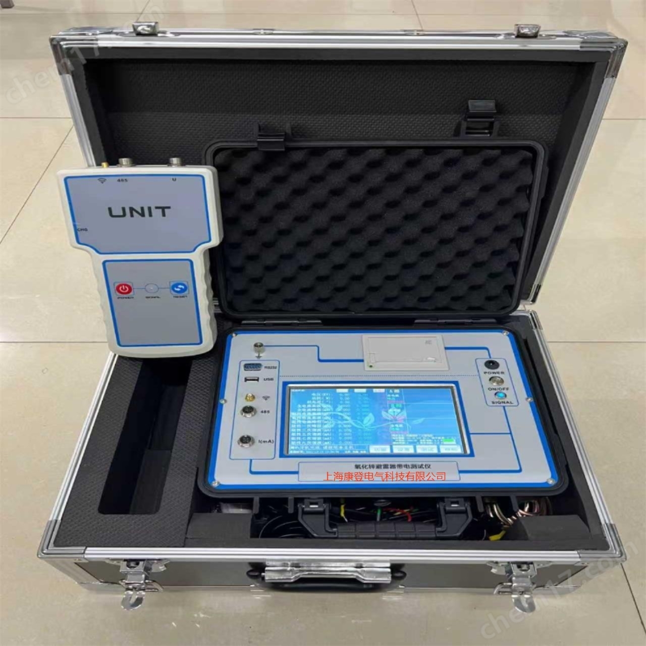
Winding inter turn impulse withstand voltage tester
NegotiableUpdate on 05/14
- Model
- Nature of the Manufacturer
- Producers
- Product Category
- Place of Origin
Overview
The RZJ-6G winding turn to turn impulse withstand voltage tester meets the relevant technical requirements in national and industry standards; High output energy, especially suitable for measuring low inductance windings (coils) of large capacity motors, transformers, electrical appliances, etc;
Product Details
RZJ-6GWinding inter turn impulse withstand voltage testerKey Features:
1. Meet the relevant technical requirements in national and industry standards;
2. High output energy, especially suitable for measuring low inductance windings (coils) of large capacity motors, transformers, electrical appliances, etc;
3. Equipped with forward and reverse testing functions, it solves the problem of uneven distribution of impulse voltage in the winding and improves testing accuracy;
4. The main circuit adopts a single tube switching output, which reduces the asymmetry of the instrument itself to zero and improves the testing accuracy;
5. By adopting the switching circuit of each phase winding and electric voltage regulation technology, the testing of each phase winding can be completed in one wiring, improving work efficiency;
6. Suitable for the detection of single/three-phase AC/DC motors, transformers, and electrical coils, improving the applicability of the instrument;
7. The use of a universal oscilloscope has improved the reliability and stability of the entire machine.
8. Optional digital storage oscilloscope, capable of storing standard waveforms of reference objects, accurately analyzing, storing, and outputting waveforms;
9. Optional built-in programmable controller (LPC) for automatic testing function.
RZJ-6GWinding inter turn impulse withstand voltage testerTechnical Specifications
RZJ-6GThe winding turn to turn impulse voltage tester is suitable for testing voltage1140VInsulation testing of winding turns for micro motors, small and medium-sized motors, and DC motors below; It can also be used for inter turn insulation detection of transformer windings and electrical coil windings.
1. Due toRZJ-6GThe tester is equipped with high voltage electricity during use, and special attention should be paid to safety during testing. Non charged metal shell components must be reliably and well grounded. Before connecting the power supply, please carefully read the user manual and strictly follow the instructions for operation.
2. Before connecting the power supply, it is necessary to check whether the power supply voltage is220V(Best configuration)500VACheck the reliability and good grounding of the AC stabilized power supply, and ensure that the foot switch is connected correctly. After confirming that everything is correct, proceed with testing the sample according to the diagram4Or picture5The wiring connection.
3. Connect the power cord plug of the test interturn tester220VPower on, then place the power switch of the interturn instrument with lock in the "ON" position, that is, turn on the power. At this time, the green indicator light of the power is on, and the oscilloscope has a scanning line display. The interturn gauge is in a preheated state, approximately8minThe preheating indicator light is on, and the interturn gauge can start working. At this time, press the "voltage drop" button, and the voltage reading should be0V.
4. Press each button from left to right and observe if the corresponding indicator light for each button is on.
5. Press the "Power Monitoring" button and adjust the voltage indication value of the turn to turn gauge to under no-load condition100VAt this point, if the test voltage is displayed as3kV+5%If the voltage of the power grid is normal, measures should be taken, such as adding a voltage regulator at the input end of the power supply.
6. First press the "Self calibration" self-locking button, and the corresponding indicator lights up. Then press the "High voltage press" and step on the foot switch. At this time, there is a high-voltage output. Then adjust the "Boost" button to make the peak voltmeter display as follows1KVAt this moment, put“V/div”Put it on0.5V/divFile, oscilloscope's "μt/div”Put it on20Ms/divOne file, there should be1VDisplay of left and right shock wave waveforms (see waveform diagram for details)data1)The interturn gauge is working properly.
7. Positive test: When the "positive test" button is pressed, the high voltage pulse test voltage of the three-phase motor isATheBTheCEnter the tested motor; When using a single-phase motor, the high-voltage pulse test voltage is determined by the mainADeputyA, Master`ADeputy`AEnter the tested motor.
8. Reverse test: When the "reverse test" button is pressed, the high voltage pulse test voltage of the three-phase motor isaThebThecEnter the tested motor; When using a single-phase motor, the high-voltage pulse test voltage is determined by the mainBDeputyB, Master`BDeputy`BEnter the tested motor.
9. Three phase motor testing selection: First press the "forward test" or "reverse test" button, and then press“A—B”Button, the indicator light in the corresponding button is on. Press the "High Voltage Press" button and step on the foot switch to turn on the high voltage output, adjust the "Boost" controller, and make the peak meter indicate the required amplitude of the applied shock wave. At this point, select the appropriate one on the oscilloscope“V/div”And“t/div”Set the gear to make it easier to distinguish differences in the observed shock wave attenuation oscillation waveform, and then release it“A—B”Button, press it“B—C”Or“C—A”Button, repeat the above experiment. If the waveforms of the two experiments are almost identical, it is considered qualified“A—B”Coincidentally, and“B—C”Or“C—A”Not overlapping, i.e“C”The phase winding corresponding to the output terminal has a fault.
Similarly, as“B—C”重合, “A—B”Or“C—A”Non overlapping means“A”If there is a fault in the winding of the corresponding phase at the output end, and none of them coincide, it indicates that there is a fault in the winding of two or more phases. (Note: The normal situation for "high voltage press" at each output level is1—5Seconds; If careful observation is required, it is generally not advisable to exceed10In seconds. Note:Release the 'high pressure press' when changing phases.)
10. Disconnect the 'high voltage press', release the foot switch, remove the test item after the test is completed, and then connect it to the next motor to be tested for the second motor test, and so on.
11. When measuring a DC motor, use a forward test according to the diagram6Connect the wires as shown, then press“A-B”Press the button to conduct the experiment. After the waveform appears, use the storage function of the oscilloscope to store the waveform as the standard waveform. Then move the output clamp to perform another winding test with the same number of pieces. If the waveforms coincide, it indicates that the insulation is intact; otherwise, it indicates that the insulation is faulty. And so on.
12. To test motors with different impedances, it is necessary to adjust the oscilloscope“LEVEL”To stabilize the waveform display, please refer to the random file for specific adjustment methodsDS1052EEasy operation manual for oscilloscope.
Wiring method of RZJ-6G winding turn to turn impulse voltage tester

Testing method for RZJ-6G winding turn to turn impulse voltage tester

Technical parameters of RZJ-6G winding turn to turn impulse voltage tester
Instrument model |
RZJ-6G |
power supply voltage |
220V±5%;50Hz |
Output test voltage |
0~6kV±5%Continuously adjustable within the range |
Shock wave pulse |
25Hz |
Energy storage capacitor |
0.22uF(Alternatively, you can choose according to your requirements) |
Maximum output energy |
3.96J |
insulation resistance |
The insulation resistance of the power output terminal to the rack is ≥20MΩ |
dielectric strength |
The power input terminal can withstand the rack1500V/50Hz,1minNo flying fox or breakdown phenomenon in the withstand voltage test |
ambient temperature |
0~35℃ |
relative humidity |
≤80% |
External dimensions(mm) |
648×520×335 |
style |
desktop |
Scope of application |
Inter turn impulse withstand voltage test of magnetic pole coil |
RZJ-6G winding turn to turn impulse voltage testerFault can be detected: inter turn insulation breakdown (inter turn short circuit); Corona discharge; Winding breakage; Difference in number of turns | |
|
RZJ-6G winding turn to turn impulse voltage testercharacteristic: 1.The main circuit adopts a single tube switching output, which reduces the asymmetry of the instrument itself to zero and improves the testing accuracy; 2.Adopting Nanjing772The factory produces high-voltage thyristors as high-voltage switch tubes to improve overall performance; 3.The use of a color digital LCD oscilloscope for waveform display significantly improves the reliability and stability of the instrument; 4.Having forward and reverse testing kinetic energy, it solves the problem of uneven distribution of impulse voltage in the winding and improves testing accuracy; 5.single/Three phase, alternating current/The universal use of DC motors greatly improves the applicability of the instrument. | |
Provide relevant training and safety operating procedures. | |