-
E-mail
1578939544@qq.com
-
Phone
136-7182-5945
-
Address
No. 155 Henggang Road, Sijing Town, Songjiang District, Shanghai
Product Categories
Shanghai Shihong Instrument Co., Ltd

Vortex flowmeter flange type
NegotiableUpdate on 06/18
- Model
- Nature of the Manufacturer
- Producers
- Product Category
- Place of Origin
Overview
Flange type, the flowmeter housing and flange material are both made of 304 stainless steel, and the instantaneous flow rate is displayed on site, DN15-300.
Product Details
Vortex FlowmeterWidely applicable to the measurement and control of superheated steam, saturated steam, compressed air, general gases (oxygen, nitrogen, hydrogen, natural gas, coal gas, etc.), water, and liquids (such as water, gasoline, alcohol, benzene, etc.) in industries such as petroleum, chemical, metallurgical, thermal, textile, paper, etc.
Vortex flowmeter flange typeUsually, this configuration is only chosen when the on-site design of the working conditions requires the use of flange type.
Vortex flowmeter flange typeThe material of the flowmeter housing and flange is 304 stainless steel, and 316/316L stainless steel can also be customized according to needs, mostly used for large diameters; Compared to commonly usedCard mounted connection vortex flowmeterThe price is slightly higher and the weight is also much heavier. We can customize various specifications of flanges such as national standard and American standard according to the requirements of on-site working conditions. During installation, it is necessary to equip fasteners such as flanges, bolts, and nuts.
Vortex flowmeter flange type:There are on-site display type, pulse output type, battery powered type, 485 communication output type, online voltage stabilization compensation type, electric remote transmission type, etc., which can be selected according to your own needs.
The price of flow meters varies with the selection specifications, caliber, and configuration, and is not a fixed price product. It needs to be selected and quoted according to your operating conditions.
Flange type vortex streetflowmeterCommon model: HVS-SG100F11U
Model annotation: Vortex flowmeter, flange type, medium is gas, DN100, The casing and flange of the flowmeter are made of 304 stainless steel, with a medium temperature of room temperature and a rated pressure of 1.6MPa; On site display of instantaneous flow and cumulative flow, 4-20mA output, 24V power supply, requiring self installation of flanges, bolts, nuts and other fasteners.
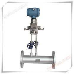
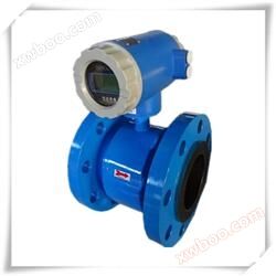
vortex streetflowmeterProduct shooting:

Required parameters for selection:
Name and composition of the tested medium; Minimum, common, and maximum flow rates under working conditions, minimum, common, and maximum pressure and temperature of the medium, pipeline material, pipeline inner diameter, display mode, and signal output configuration.
Working principle
If a non streamlined vortex generator (flow resistant fluid) is set up in the fluid, two columns of regular vortices are alternately generated from both sides of the vortex generator. This type of vortex is called a Karman vortex street, as shown in Figure (1).

Figure (1)
The vortices are arranged asymmetrically downstream of the vortex generator. Assuming the frequency of vortex occurrence is f, the average velocity of the incoming flow of the measured medium is V, the width of the upstream face of the vortex generator is d, and the diameter of the body is D, according to the principle of Karman vortex street, the following relationship is obtained:
Formula (1) for f=StV/d
In the formula:
F - frequency of Karman vortex generated on one side of the body
St Strouhal number (dimensionless number)
V - Average flow velocity of fluid
D - width of vortex generator
From this, it can be seen that the instantaneous flow rate can be calculated by measuring the separation frequency of the Karman vortex street. Among them, Strouhal number (St) is an dimensionless unknown variable,

Figure (2) shows the relationship between Strouhal number (St) and Reynolds number (Re).
In the straight part of the curve table with St=0.17, the frequency of vortex release is proportional to the flow velocity, which is the measurement range of the vortex flow sensor. As long as the frequency f is detected, the flow velocity of the fluid inside the pipe can be obtained, and the volumetric flow rate can be calculated from the flow velocity V. The ratio of the measured number of pulses to the volume is called the instrument constant (K), as shown in equation (2)
K=N/Q (1/m ³) formula (2)
In the formula: K=instrument constant (1/m ³).
N=number of pulses
Q=Volume flow rate (m ³)
Specification

Determination and installation design of instrument caliber
Instrument selection is a highly valued task in instrument applications, and the correctness of instrument selection will directly affect whether the instrument can operate normally Therefore, when users and design units choose our company's products, please carefully read the information in this section, carefully check the process parameters of the fluid, and feel free to contact our sales or technical support department at any time to ensure the correct selection.
1、 Determination of applicable flow range and instrument diameter
The selection of instrument caliber is determined based on the flow range. The measurement range of vortex flowmeter with different calibers is different. Even if the same caliber flowmeter is used for different media, its measurement range is also different. The actual measurable flow range needs to be determined through calculation.
(1) The flow range of air and water under reference conditions is shown in Table (2), and the reference conditions are as follows:
1. Gas: Normal temperature and pressure air, t=20 ℃, P=0.1MPa (absolute pressure), ρ=1.205 kg/m3, υ=15 × 10-6 m2/s.
2. Liquid: Room temperature water, t=20 ℃, ρ=998.2kg/m3, υ=1.006 × 10⁻⁶m2/s.
(2) The basic steps for determining the flow range and instrument diameter are:
1. Clearly define the following working parameters.
(1) Name and composition of the tested medium
(2) Minimum and commonly used working conditions、maximum flow
(3) Minimum, common, and maximum pressure and temperature of the medium
(4) Viscosity of the medium in working condition
2. The vortex flowmeter measures the working state volume flow rate of the medium, so the working state volume flow rate of the medium should be calculated based on the process parameters first. The relevant formula is as follows:
(1) Given the standard state volumetric flow rate of a gas, the operating condition volumetric flow rate can be calculated using the following formula
 Formula (3)
(2) Given the standard state density of the gas, ρ, the operating density can be calculated using the following formula

(3) Convert the known mass flow rate Qm to volume flow rate Qv

In the formula:
Qv: Volume flow rate of the medium under operating conditions (m3/h)
(Qv=3600f/K K: Instrument coefficient)
Qo: Volume flow rate of the medium under standard conditions (Nm3/h)
Qm: Mass flow rate (t/h)
ρ: Density of the medium under working conditions (kg/m3)
ρ o: Density of the medium in standard state (kg/m3), standard state density of commonly used gas media, as shown in Table (3)
P: Operating condition gauge pressure (MPa)
t: Operating condition temperature (℃)
3. Determination of the lower limit flow rate of the instrument. The upper limit of the applicable flow rate of vortex flowmeter is generally not calculated, and the selection of the diameter of vortex flowmeter is mainly for the calculation of the lower limit of flow rate. The calculation of the lower limit flow rate should meet two conditions: the minimum Reynolds number should not be lower than the limit Reynolds number (Re=2 × 10⁴); The vortex intensity generated by the stress type vortex flowmeter at the lower limit flow rate should be greater than the allowable value of the sensor vortex intensity (the vortex intensity is proportional to the lift ρ v2). These conditions can be expressed as follows:
The measurable lower limit flow rate for operating conditions determined by density:

Linear lower limit flow determined by kinematic viscosity:
 Formula (7)
In the formula:
Q ρ: Minimum volumetric flow rate (m3/h) that meets the requirements of vortex strength
ρ 0: Density of the medium under reference conditions
Q υ: Minimum linear volumetric flow rate (m3/h) that meets the minimum Reynolds number requirement
ρ: Density of the tested medium under working conditions (kg/m3)
Q0: Minimum volumetric flow rate of the instrument under reference conditions
(m3/h)
υ: Kinematic viscosity of the medium under working conditions (m2/s)
υ o: Kinematic viscosity of the medium under reference conditions (m2/s)
Calculate Q ρ and Q ν using formulas (6) and (7). Compare Q ρ and Q ν to determine the measurable lower limit flow rate and linear lower limit flow rate of the flow meter:
Qυ≥QρThe measurable flow range is Qρ~Qmax , The linear flow range isQυ~Qmax
Qυ<Qρ: Measurable flow range andThe linear flow range is
Qρ~Qmax
Qmax: Upper limit volume flow rate of vortex flowmeter(m3/h)
4. The upper limit flow rate of the instrument shall be based on the upper limit flow rate in Table (2) The upper limit flow rate of gas should be less than 70m/s, and the upper limit flow rate of liquid should be less than 7m/s
When the medium measured by the user is steam, the commonly used unit of measurement is mass flow rate, which is t/h or Kg/h. Due to the varying densities of steam (superheated steam and saturated steam) at different temperatures and pressures, the determination of the steam flow range can be calculated using formula (8)
 Formula (8)
In the formula:
ρ: Density of steam (kg/m3)
ρ0:1.205kg/m3
Q Steam: Steam mass flow rate (t/h)
6. Calculate the pressure loss and detect whether the pressure loss has an impact on the process pipeline. Formula (unit: Pa):
Δ p=Cd ρ V2/2 formula (9)
In the formula:
ρ: Density of working medium (kg/m3)
V: Average flow velocity (m/s)
When the measured medium is a liquid, in order to prevent gasification and cavitation, the pipeline pressure should meet the following requirements:
Formula (10) for p ≥ 2.7 Δ p+1.3p0
In the formula:
Δ p: pressure loss (Pa)
P0: Saturated vapor pressure of liquid at operating temperature (Pa absolute pressure)
Po: Vapor pressure of fluid (Pa absolute pressure)
8. Vortex flowmeters are not suitable for measuring high viscosity liquids. When the calculated lower limit of measurable flow does not meet the design process requirements, other types of flow meters should be considered for selection.
9. If both calibers can meet the requirements through calculation, in order to improve measurement efficiency and reduce costs, the smaller caliber meter should be selected. It should be noted that the commonly used amount should be kept at 1/2 to 2/3 of the upper limit of the flow range as much as possible
Δ p: pressure loss (Pa) Cd: pressure loss coefficient
Example of selection:
Example 1:When the gas pressure, temperature, and flow rate under standard conditions are known
A certain compressed air has a standard flow rate range of QN=1200-12000Nm3/h, pressure P=0.7Mpa (gauge pressure), and temperature t=30 ℃. Try to determine the diameter of the flowmeter.
Step 1: Calculate the working condition volume flow rate of compressed air
According to formula (3):
The lower limit volume flow rate for operating conditions is:
Qvmin=QN×0.101325×(273.15+t)/293.15/(P +0.1)
=1200×0.101325×(273.15+30)/293.15/(0.7 +0.1)
=157(m3/h)
The upper limit of flow rate for operating conditions is Qvmax=1570 (m3/h)
Step 2: Based on the operating flow range of 157-1570m3/h, refer to Table (2). The flow meters that meet the lower limit flow conditions are DN80, DN100, and DN125. Considering the upper limit flow rate of 1270m3/h, usage effect, and economic cost, DN100 is initially selected. The operating flow range of DN100 flow meter is 100-1700m3/h, which is close to the operating flow range. DN100 flow meter is initially selected, but the measurable lower limit flow of DN100 flow meter under this operating condition should be specifically calculated. Calculate the measurable lower limit flow rate of DN100 flowmeter under this operating condition:
According to formulas (4) and (6):

That is, the measurable lower limit flow rate of the flowmeter under this operating condition is 37.46m3/h, which is much lower than the required lower limit flow rate of 157m3/h. Therefore, it is determined to use a DN100 flowmeter.
Example 2: When the steam pressure, temperature, and operating flow rate are known
The measuring medium is superheated steam, with a steam temperature of 320 ℃, a pressure of 1.5MPa (absolute pressure), and a flow range of 3t/h to 25t/h. Determine the diameter of the flow meter.
Step 1: Calculate the volumetric flow range of steam under the equivalent air reference condition. According to Appendix (2), the density of steam in this state is 5.665 Kg/m3, as calculated by formula (8):

Step 2: According to the equivalent reference flow range of 765-6379m3/h, refer to Table (2) and find that the DN200 caliber is more suitable for this flow range.


Installation design of instruments
The correct installation of instruments is an important part of ensuring their normal operation. If not installed properly, it can affect the accuracy of instrument use, and in severe cases, it can affect the service life of instruments and even damage them.
(1) Installation environment requirements:
1. Try to avoid strong electrical equipment, high-frequency equipment, and strong switching power supply equipment as much as possible. The power supply of the instrument should be separated from these devices as much as possible.
2. Avoid direct effects from high-temperature heat sources and radiation sources. If installation is necessary, insulation and ventilation measures must be taken.
3. Avoid high humidity and strong corrosive gas environments. If installation is necessary, ventilation measures must be taken.
4. Vortex flow meters should be avoided from being installed on pipelines with strong vibration as much as possible. If installation is necessary, pipeline fastening devices must be installed at 2D upstream and downstream locations, and anti vibration pads must be added to enhance the anti vibration effect.
5. It is recommended to install the instrument indoors and pay attention to waterproofing when installing outdoors. Special attention should be paid to bending the cable into a U-shape at the electrical interface to prevent water from entering the amplifier housing along the cable.
6. There should be ample space around the instrument installation point for wiring installation and regular maintenance.
(2) Installation requirements for instrument pipelines:
1. Vortex flowmeter has certain requirements for the upstream and downstream straight pipe sections of the installation point, otherwise it will affect the flow field of the medium in the pipeline and affect the measurement accuracy of the instrument. The length requirements for the upstream and downstream straight pipe sections of the instrument are shown in Figure (III)

Note: The regulating valve should not be installed upstream of the vortex flowmeter as much as possible, but should be installed at 10D downstream of the vortex flowmeter.
1. The inner diameter of the upstream and downstream piping should be the same. If there is a difference, the inner diameter Dp of the piping and the inner diameter Db of the vortex instrument body should meet the following relationship
0.98Db≤Dp≤1.05Db
The upstream and downstream piping should be concentric with the inner diameter of the flow meter body, and the different axial degrees between them should be less than 0.05Db
The sealing gasket between the instrument and the flange should not protrude into the pipe during installation, and its inner diameter should be 1-2mm larger than the inner diameter of the body
3. Installation design of pressure and temperature measuring holes. When temperature and pressure transmitters need to be installed on the tested pipeline, the pressure measuring hole should be set at 3-5D downstream, and the temperature measuring hole should be set at 6-8D downstream, as shown in Figure (7). D is the gauge diameter of the instrument, unit: mm
4. Instruments can be installed horizontally, vertically, or diagonally on pipelines.
When measuring gas, instruments should be installed in vertical pipelines with no restrictions on gas flow direction. But if the pipeline contains a small amount of liquid, in order to prevent the liquid from entering the instrument measuring tube, the airflow should flow from bottom to top, as shown in Figure (4a)
When measuring liquids, in order to ensure that the tube is filled with liquid, instruments should be installed in vertical or inclined pipelines to ensure that the direction of liquid flow is from bottom to top. If the pipeline contains a small amount of gas, in order to prevent gas from entering the instrument measuring tube, the instrument should be installed at a lower part of the pipeline
As shown in Figure (4b)

When measuring high and low temperature media, attention should be paid to insulation measures. The high temperature inside the converter (inside the header housing) should generally not exceed 70 ℃; Low temperature can easily cause condensation inside the converter, reducing the insulation impedance of the printed circuit board and affecting the normal operation of the instrument.
Real photos of products in the same series:

(On site display type)

(Clamping type complete set of configuration)

(Sanitary type)

(Flange type)

(High temperature type)
 ,
,
(Online voltage stabilization compensation type)

(Different calibers)

, (anti-corrosion type)

(Split type voltage stabilization compensation)

(Insertion type)
After sales and warranty
Shanghai Shihong Instrument Co., LtdAll products supplied: Provide free telephone consultation, guidance on installation and debugging services; Negotiate on-site guidance for installation, debugging, and other matters, and only charge reasonable travel expenses; Large quantities can provide free on-site guidance for installation and debugging. Service Objective:No matter how long the product is used, as long as you find us, we will solve all your problems until you are satisfied. We believe that our years of practical experience in the flowmeter industry can bring you satisfactory services. 24-Hour Hour Hotline:(Same WeChat account)
- About Us
- Company Profile
- Contact Us
- Company News
- Factory Display
- Product Center
- High pressure flowmeter
- Gas flow meter
- Sewage flow meter
- Mechanical flowmeter
- Steam flow meter
- News Center
- Technical articles
- Company News
- Data Download
- Contact Us
- Contact address: 155 Henggang Road, Sijing Town, Songjiang, Shanghai
- Sales Phone: Fax:
- Sales Manager: 136-7182-5945
- Technical Support: 185-1625-6865
-

24-hour WeChat (WeChat ID:) is available online anytime, anywhere to provide you with professional flow meter services.
Record number of the Ministry of Public Security: 3101170202786 Record number:Shanghai ICP Registration No. 15021440-1Copyright ? 2002-2023 Shanghai Shihong Instrument Co., Ltd., all rights reserved