-
E-mail
bj6213@126.com
-
Phone
13261994018
-
Address
Room 305, Building 22, No. 10 Rongcheng North Road, Huairou District, Beijing
Product Categories
- High standard farmland construction equipment
- Plant Protection Meteorological Station
- Meteorological monitoring equipment
- Micro meteorological station
- ultrasonic sensor
- Integrated water and fertilizer equipment
- air quality
- Integration of water and fertilizer
- Plant protection equipment and instruments
- meteorological equipment
- sensor
- Soil equipment
- Plant protection instruments and equipment
- Hydrology and Water Conservancy
- Soil moisture, soil moisture, hardness, compactness equipment
- Smart Agriculture
Beijing Mengchuang Weiye Technology Co., Ltd
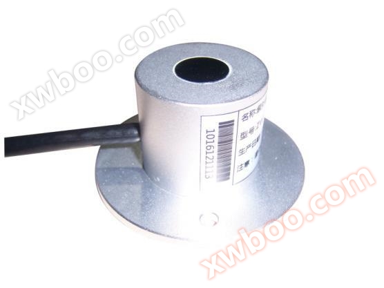
UV radiation sensor
NegotiableUpdate on 05/07
- Model
- Nature of the Manufacturer
- Producers
- Product Category
- Place of Origin
Overview
UV radiation sensor
Product Details
- Product Introduction
Our company solemnly promises that for users who purchase our sensors, we will provide free one-on-one service
Technical support (knowledge of wiring methods, data analysis, maintenance, etc.) until the user masters the use.
Product Introduction
 MC-ZWThe ultraviolet radiation sensor adopts a photoelectric detector to receive ultraviolet light wave electrical signalsThis productUsed to measure solar ultraviolet radiation in the atmosphere(UVABPrecision instruments within the wavelength range, when used in conjunction with data acquisition devices, can provide information of public concernUVIndexUVRed spot measurement,UVThe impact on the human body andUVDue to its unique biological and chemical effects, it has received great attention from meteorology, industry, architecture, and medicine, and is widely used in the study of erythema dose caused by exposure to sunlight, comprehensive environmental ecological effects, climate change, as well as ultraviolet monitoring and forecasting.
Technical Parameter
Measurement range:0~200W/m2
spectral range:280~400nm
divide distinguish Rate:1W/m2
accurate true Degree:±5%
Cosine response:≤4%The solar altitude angle is30When (°)
response time:≤1S(99%)
Power supply mode:□DC5V
□DC12V
□DC 24V
□ other
Output format:□ voltage:0-2.5V
□ voltage:0-5V
□ electric current:4-20mA
□ RS485
□ other
Working environment: Temperature-50℃~50℃
Rated voltage:300V
Temperature level:80℃
calculation formula
Voltage type(0~2.5Voutput):
E= V /2.5 ×200
(ETo measure radiation values(W/m2),VTo output voltage(V))
Current type(4~20mAoutput):
E=(I-4)/ 16×200
(ETo measure radiation values(W/m2),ITo output voltage(mA))
wiring method
(1)If equipped with the collector produced by our company, simply connect the sensor to the corresponding interface on the collector using a sensor cable.
(2)If purchasing a transmitter separately, the transmitterThe supporting line sequence is as follows:
|
Line color |
output signal |
||
|
voltage source |
current mode |
Communication type |
|
|
red |
Power supply positive |
Power supply positive |
Power supply positive |
|
black(Green)colour |
Power Ground |
Power Ground |
Power Ground |
|
yellow |
voltages |
current signal |
A+/TX |
|
blue |
|
|
B-/RX |
(3)Pulse voltage and current output wiring methods:

(Voltage, pulse wiring)

(Wiring of current output mode)
structure size

Transmittersize


countCRCSteps for coding:
1Pre set16The bit register is in hexadecimal formatFFFF(i.e. all are)1). Call this registerCRCRegister;
2Take the first one8Bit data and16positionCRCIf the low bits of the register are different, place the result inCRCRegister;
3Move the contents of the register to the right by one bit (towards the lower position), using0Fill in the highest position and check the lowest position;
4If the lowest position is0: Repeat step3Step (Move Again)
If the lowest position is1:CRCRegister and PolynomialA001( 0000 0001)Perform XOR;
5Repeat the steps3and4Until it moves to the right8Next time, this is the whole thing8All data has been processed;
6Repeat the steps2To Step5, proceed to the next step8Processing of bit data;
7The final result obtainedCRCThe register isCRCCode;
8, willCRCWhen the result is placed in the information frame, the high and low bits are swapped, with the low bits coming first.


