- Phone
-
Address
Room 601, No. 23, Lane 1288, Xinyuan Road, Jiading District, Shanghai
Product Categories
Shanghai Ruidan Automation Instrument Co., Ltd
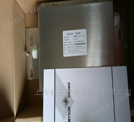
Toledo adapter junction box
NegotiableUpdate on 05/19
- Model
- Nature of the Manufacturer
- Producers
- Product Category
- Place of Origin
Overview
The AJB series junction box produced by Mettler Toledo is used in analog sensor weighing systems. Due to the fact that the rated output and output impedance parameters of the sensors cannot be consistent in manufacturing, if a scale consists of multiple sensors, when the load is located at different positions on the scale, it may cause inconsistent readings of the weighing instrument. We call this inconsistency angle difference. For this purpose, our company has developed a dedicated junction box, which first connects the output signal of the sensor to the junction box and then sends it to the instrument. Adjust the angle difference by adjusting the corresponding potentiometer in the junction box.
Product Details
Toledo adapter junction boxMettler-Produced by ToledoAJBSeries junction boxes are used in analog sensor weighing systems. Due to the fact that the rated output and output impedance parameters of the sensors cannot be consistent in manufacturing, if a scale consists of multiple sensors, when the load is located at different positions on the scale, it may cause inconsistent readings of the weighing instrument. We call this inconsistency angle difference. For this purpose, our company has developed a dedicated junction box, which first connects the output signal of the sensor to the junction box and then sends it to the instrument. Adjust the angle difference by adjusting the corresponding potentiometer in the junction box.
Model and Naming
AJB-003 junction box, also known as adapter junction box;
AJB-005 junction box, suitable for weighing instruments with no more than 4 sensors;
AJB-007 junction box, suitable for weighing instruments with no more than 6 sensors.
For electronic scales with more than 6 sensors, multiple junction boxes can be combined to adjust the angle difference.
3.0 Technical Indicators
Stainless steel shell, dedicated sealed joint, waterproof and dustproof. Protection level: IP65.
Using high-precision, low-temperature drift resistors and potentiometers to protect the accuracy and stability of the system's operation.
The connection method between sensor wires and signal cables is: terminal block. There are signal markings next to the wiring terminals to ensure convenient wiring and reliable contact.
4.0 Installation, Debugging, and Maintenance
4.1 Open box inspection
Please first check if all components inside the packaging box are complete. The following components should be included in the packaging box:
1 junction box
1 copy of user manual
If components are missing or damaged, please contact the nearest Mettler-Contact Toledo office.
4.2 Installation
Fix the junction box in the appropriate position on the scale body, open the top cover of the junction box, thread the sensor cable and instrument signal cable through the corresponding interfaces of the junction box, and connect all cables according to the wiring diagram given in Section 5.0. Tighten the outer shielding of all cables to the grounding screw of the junction box, while ensuring that the outer shell of the junction box is reliably grounded. The resistance from the grounding wire to the junction box is less than 1 ohm,The grounding resistance of the junction box grounding pile shall not exceed4 ohms!
The names and colors of cable cores are shown in the following table:
Core wire name |
Positive motivation |
negative incentive |
positive feedback |
negative feedback |
Positive signal |
negative signal |
block |
English code |
+EXC |
-EXC |
+SEN |
-SEN |
+SIG |
-SIG |
SHLD |
Core wire color |
green |
black |
yellow |
blue |
white |
red |
yellow/Green |
4.3 Angle difference adjustment
Place the test weights as close as possible to each sensor and record the instrument readings. Note that the method of adding sensing weights should be used to make the readings accurate to 0.1d, or directly record the internal division degree displayed on the instrument. Then, according to the metrological regulations, adjust the corresponding potentiometer of the sensor (clockwise rotation increases the reading, counterclockwise rotation decreases the reading), so that the angle difference is within the specified range (generally not exceeding 0.5d). The corresponding relationship between potentiometers and sensors is shown in the wiring diagram in Section 5.0. (Note: Do not turn the potentiometer too far)
4.4 Installing the upper cover and sealing joint
After debugging, cover the junction box and tighten the screws. The tightening force of each screw should be balanced. The unused interface sealing joints of the junction box should be blocked with sealing rubber gaskets, and the nuts of each sealing joint should be tightened at the same time, otherwise it will affect the sealing performance.
Regularly check the sealing condition of the junction box, and it is recommended to tighten the fixing screws and sealing joint nuts on the top cover of the junction box at least every six months to maintain the sealing of the junction box.


