- Phone
-
Address
Building 2, No. 64 Tiancheng Road, Jianggan District, Hangzhou City, Zhejiang Province
Product Categories
Hangzhou Hangrui Electric Power Automation Co., Ltd
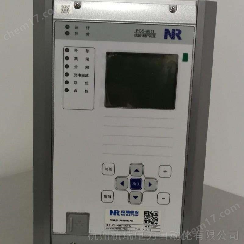


Nanjing Nanrui Jibao RCS9611CS protection device
NegotiableUpdate on 05/14
- Model
- Nature of the Manufacturer
- Producers
- Product Category
- Place of Origin
Overview
The Nanjing Nanrui Jibao RCS9611CS protection device $r $n can select whether to exit the current protection of this section's compound voltage interlock and direction interlock to become pure overcurrent protection or directly exit the current protection when the bus PT is disconnected through the control word "PT disconnection current protection". The "current protection" referred to here refers to the current protection sections that have been locked with compound voltage or directional locking. The current protection section that does not have either overvoltage or directional locking is not affected by this control word.
Product Details
Nanjing Nanrui Jibao RCS9611CS protection device
2.2 Zero sequence protection (grounding protection)
When the device is used in an ungrounded or low current grounded system and the zero sequence current during a grounding fault is very small, the grounding test function can be used to isolate the fault. This situation requires the zero sequence current to be introduced by an external dedicated zero sequence CT, which cannot be produced by software itself.
When the device is used in a low resistance grounding system and the grounding zero sequence current is relatively large, the direct tripping method can be used to isolate the fault. Correspondingly, this device provides three-stage zero sequence overcurrent protection, where zero sequence section I and zero sequence section II are fixed as definite time limit protection, and zero sequence section III can be selected as definite time limit or inverse time limit through control words. The selection of inverse time limit characteristics is the same as that of overcurrent section III mentioned above.
The zero sequence section III can be selected by the control word to trip or alarm.
When the zero sequence current is used for tripping and reporting, it can be introduced by an external dedicated zero sequence CT or generated by software (there is a "zero sequence current self generated" control word in the system setting).
2.3 Overload protection
The device is equipped with an independent overload protection, which can be selected by the control word to alarm or trip. After the overload outlet trips, it locks and closes again.
2.4 Acceleration protection
The device is equipped with an overcurrent acceleration protection and a zero sequence acceleration protection.
The reclosing acceleration can be selected as either pre reclosing acceleration or post reclosing acceleration. If you choose to accelerate before, put it into operation before the reclosing action; If acceleration is selected, it will be activated for 3 seconds after the reclosing action.
Hand on acceleration is fixed for 3 seconds during hand on.
2.5 Low cycle protection
The device is equipped with a low cycle protection through low voltage lockout and frequency slip lockout. The control word ("DF/DT lockout input") can be used to select whether to lock the low cycle protection when the frequency drops beyond the slip lock value. The low voltage lockout function is fixedly activated.
The device provides a "low cycle load reduction" hard pressing plate to activate and deactivate low cycle protection.
After the low cycle protection action, the lock is closed again.
Nanjing Nanrui Jibao RCS9611CS protection device
2.6 Reclosing the switch
The device provides a three-phase primary reclosing function, with two starting modes: non corresponding starting and tripping outlet 1 protection action starting.
The reclosing method includes three types: no detection, no voltage detection of the line, and synchronous detection.
The recloser is activated after charging is completed. When the line is in normal state (KKJ=1, TWJ=0) and there is no lockout signal, it will run for 15 seconds before charging. The following signals are locked and reclosed:
1> Hand jumping or remote jumping; 2> Lock the reclosing switch in; 3> Control circuit disconnection; 4> Low cycle protection action; 5> Overload tripping; 6> The spring has not stored energy and is open; 7> Line PT disconnection (when there is no voltage on the line or when the line is put into operation at the same time); 8> High week protection action.
2.7 Busbar Low Voltage Protection
The device provides a low-voltage protection, and when the bus line voltage is lower than the low-voltage setting value, the low-voltage protection will be activated for a set time. Low voltage protection can choose whether to use current lockout. If current lockout is enabled, the low voltage protection is only allowed to operate when the current is less than the lockout value. When the three-phase PT is disconnected, the device can automatically identify and lock the low-voltage protection. The device provides a "low voltage protection" hard pressing plate to achieve the switching of this function.
2.8 Bus Overvoltage Protection
The device provides a section of overvoltage protection. When the bus line voltage is higher than the bus overvoltage setting value, the bus overvoltage protection will be activated for a set time. The device provides a "overvoltage protection" hard pressing plate to achieve the switching of this function.
2.9 Zero sequence overvoltage protection
The device provides a zero sequence overvoltage protection, and the zero sequence voltage is generated by the three-phase voltage itself. When the zero sequence voltage of the busbar is higher than the zero sequence overvoltage setting value, the set time zero sequence overvoltage protection will be activated. The device provides a "zero sequence overvoltage" hard pressing plate to achieve the switching of this function.
2.10 High cycle protection
The device provides a high cycle protection, and when the system frequency is higher than the high cycle set value, the set time high cycle protection will be activated. The device provides a "high cycle protection" hard pressing plate to achieve the switching of this function.
2.11 Overcurrent lockout
The protective device is equipped with a high current lockout protection function, which is used for situations where the breaking capacity of the circuit breaker is insufficient or the site is an FC circuit. When the fault current is greater than the current lockout protection setting, only the action message protection tripping outlet 1 does not operate, and other outlets do not have overcurrent lockout function. This function can be turned on or off through the "overcurrent lockout protection input" control word.
2.12 Trip Logic Matrix
The tripping mode of each protection in this device adopts a setting method, that is, which protection action and which switch to trip can be freely set as needed. RCS-9611CS standard configuration provides 2 sets of trip outlets: trip outlet 1 (CK1 "402-414") and trip outlet 2 (CK2 "427-428"). At this time, the set values "trip outlet 3" and "trip outlet 4" are invalid. When selecting BO plugins, four sets of trip outlets are provided: trip outlet 1 (CK1 "509-510"), trip outlet 2 (CK2 "525-526"), trip outlet 3 (CK3 "527-528"), and trip outlet 4 (CK4 "529-530").
Trip outlet 1 is used to trip the switch of this line, while trip outlets 2-4 can be selected by the user to trip which switch.
The setting instructions for the trip matrix are as follows:
digit1514131211109876543210
Component exportHFU0GYGYDYLFI0JSI03
_FSXI03I02I01GFHGLJSGL3
_FSXGL3GL2GL1
CK10000000011000001
CK2
CK3
CK40000000000000000
Among them, the row represents the protective element, and the list shows the outlet trip relay to be activated.
Setting method: Fill in 1 in the space between the protective component and the tripping relay to be activated, and fill in 0 in other spaces to obtain the tripping mode.
For example, if GL1 needs to act on outlet trip relay 1, then cross handle 1 in the column where GL1 is located and in the row where CK1 is located. If I01 and I02 also need to act on the outlet trip relay 1, then in the column where I01 and I02 are located and in the row where CK1 is located, cross handle 1. In this way, a 16 bit binary bit string can be obtained in the CK1 row:
CK1=0000000011000001
If a certain set of exports is not used, such as CK3, it can be completely rounded to 0, that is: 0000000000000000.
In the protection setting menu, input the above binary bit strings for CK1, CK2, CK3, and CK4 to complete the setting of the trip mode.
Similar Product Recommend