- Phone
-
Address
Building 2, No. 64 Tiancheng Road, Jianggan District, Hangzhou City, Zhejiang Province
Product Categories
Hangzhou Hangrui Electric Power Automation Co., Ltd
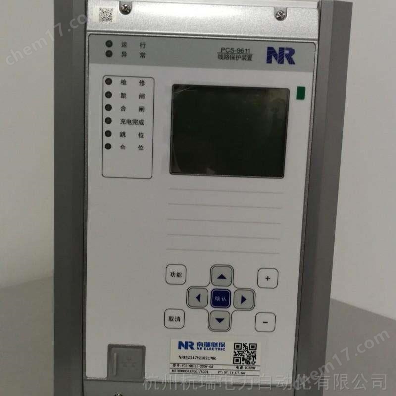


Nanjing Nanrui Jibao PCS9621 Transformer Protection and Measurement Device
NegotiableUpdate on 05/14
- Model
- Nature of the Manufacturer
- Producers
- Product Category
- Place of Origin
Overview
Nanjing Nanrui Jibao PCS9621 Transformer Protection and Measurement Device $r $nPCS-9621CS Station Transformer Protection Device is suitable for the protection and measurement of station transformers or grounding transformers in non directly grounded systems or low resistance grounded systems with voltage levels below 110kV. The device collects analog signals through conventional electromagnetic transformers and supports the IEC61850 protocol. The following figure shows a typical application configuration of this type of protective device.
Product Details
Nanjing Nanrui Jibao PCS9621 Transformer Protection and Measurement Device
1.3 Performance Characteristics
High performance general-purpose hardware, real-time computing: using a 32-bit high-performance dual core processor, Core 1 completes protection operations and
Export logic, core 2 implements functions such as event recording, fault recording, human-machine interface, backend communication, and printing. high-performance
The hardware ensures that the device performs real-time calculations on all relays at every sampling interval.
Double sampling: using double sampling and mutual calibration technology, one path is used for calculating the action behavior of protective components, and the other path is used for opening
Release the positive power supply to ensure the reliability of protective sampling and the correctness of protective behavior.
Software modular design: The device provides complete protection functions, and each protective component is designed modularly, independent of each other, and flexible
Active configuration.
Complete communication functions: With flexible communication methods, it can be equipped with 3 100Mbps Ethernet interfaces and 2 RS-485 serial ports,
1 RS-232 printing serial port. Support the communication standard DL/T667-1999 (IEC60870-5-103) and
DL/T860(IEC61850), It also supports Modbus RTU and Modbus TCP protocols. Supports 100Mbps and over 5
Class line or fiber optic communication interface.
Easy debugging and maintenance: With a friendly human-machine interface and rich PC auxiliary software, it is convenient for device setup and debugging.
1.4 Product Execution Standards
The standard for product execution is the enterprise standard of Nanjing Nanrui Jibao Electric Co., Ltd.: Q/NR C005 General Technology for Transformer Protection Device
condition
Nanjing Nanrui Jibao PCS9621 Transformer Protection and Measurement Device
working principle
The main program is divided into a normal running program and a fault calculation program: the normal running program completes state monitoring under system conditions
Auxiliary functions such as data preprocessing. After the entire group is started, it enters the fault calculation program to perform various protection algorithm calculations and trip logic judgments
Wait.
3.1 Analog Input
This device can introduce the following analog quantities: three-phase protection current (Ia, Ib, Ic), three-phase measurement current (Iam, Ibm, Icm)
Three phase bus voltage (Ua, Ub, Uc), external zero sequence voltage (U0), high voltage side zero sequence current (I0H), low voltage side zero sequence current (I0L).
The external analog input is isolated and transformed by an isolation transformer, then passed through a low-pass filter to an analog-to-digital converter, and finally sampled by the CPU at regular intervals. CPU
Process the obtained digital signals to form various protective relays.
Ia, Ib, Ic are three-phase current inputs for protection purposes; I0H can be used as both zero sequence overcurrent protection (trip or alarm) and small
Input for current grounding line selection; Iam, Ibm, and Icm are three-phase current inputs for measurement purposes; Ua, Ub, Uc are bus voltages, and the voltage can be
It can be connected in a Y-shaped or V-shaped manner, and is used as a shared protection and measurement device in this device. It calculates the form together with Iam, Ibm, and Icm
P, Q, COS ф, kWh, kVarh of cost intervals; U0 is the external zero sequence voltage; I0L is the zero sequence current on the low voltage side, used for low voltage
Side zero sequence protection.
3.2 Device start-up components
The device has set different starting elements for each protective element, and the corresponding starting elements can only be counted after they are started
Calculate. The device is equipped with dual sampling technology, with the main channel sampling data used for protection component calculation and the backup channel sampling data used for opening the outlet
Positive power supply. Only when both dual channel sampling data meet the action requirements can the outlet be tripped, otherwise it cannot be tripped.
Overcurrent protection starting element: It operates when the three-phase current value is greater than 0.95 times the set value. This startup component is used to open the corresponding
Overcurrent protection.
Positive sequence reverse time limit protection starting element: It will activate when the positive sequence current value is greater than 0.95 times the set value. This startup component is used to open
Corresponding positive and negative time limit protection.
Negative sequence overcurrent protection starting element: It operates when the negative sequence current is greater than 0.95 times the set value. This initiating component is used to open the corresponding negative
Sequence overcurrent protection.
Zero sequence overcurrent protection starting element: It operates when the zero sequence current is greater than 0.95 times the zero sequence current setting value. This startup component is used to open
Corresponding zero sequence overcurrent protection.
Low voltage side zero sequence overcurrent protection starting element: It operates when the low voltage side zero sequence current is greater than 0.95 times the zero sequence current setting value. This startup
The component is used to open the corresponding low voltage side zero sequence overcurrent protection.
Low voltage protection starting element: When the bus voltage is lower than 1.03 times the low voltage setting value, this starting element is used to open the low voltage
Pressure protection.
Zero sequence overvoltage starting element: It operates when the zero sequence voltage is greater than 0.95 times the zero sequence voltage setting value. This startup component is used to open the corresponding
Zero sequence overvoltage protection.
Chapter 3 Working Principle
Nanrui Jibao 10
Non electric protection starting element: It operates when there is a non electric input that triggers a trip. This starting component is used to open the corresponding non electrical components
Quantity protection.
3.3 Overcurrent protection
This device is equipped with three stages of timed overcurrent protection, each with independent current and time settings as well as control words. Each paragraph can be selected as
No overvoltage lockout (low voltage and negative sequence voltage).
Composite pressure component
When a remote fault occurs in the system, the fault current is relatively small, and a compound voltage control component is introduced to improve the sensitivity of protection to such faults
Sex. The overcurrent protection current setting can be reset to have a considerable sensitivity to the fault current in the event of remote faults, and can be controlled through complex voltage control
Components are used to ensure reliable operation of overcurrent protection. When the compound voltage control component is put into use, the overcurrent setting can be set to avoid the maximum load electricity
Flow is enough. The following table lists the relationship between the overcurrent components of each phase and their complex voltage control conditions.
Similar Product Recommend