- Phone
-
Address
Building 2, No. 64 Tiancheng Road, Jianggan District, Hangzhou City, Zhejiang Province
Product Categories
Hangzhou Hangrui Electric Power Automation Co., Ltd
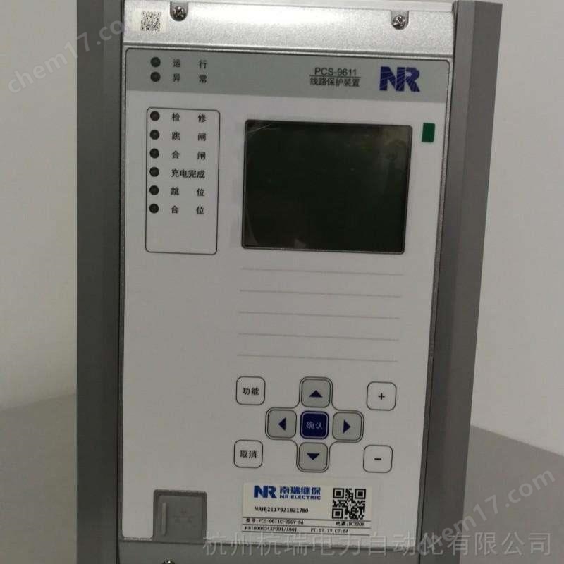


Nanjing Nanrui Jibao PCS9613 Protection Device
NegotiableUpdate on 05/14
- Model
- Nature of the Manufacturer
- Producers
- Product Category
- Place of Origin
Overview
At the moment of disconnection of Nanjing Nanrui Jibao PCS9613 protection device $r $nCT, the starting element and differential relay on the disconnected side may act, but the starting element on the opposite side does not act, and will not send a differential protection action signal to the current $r $n side, thus ensuring that the longitudinal differential will not malfunction. After a delay, the non disconnected side will report a "differential current alarm", which will be processed in the same way as the CT disconnected line $r $n. When a fault or system disturbance occurs during the disconnection or differential current alarm of $r $nCT, resulting in the action of the starting element, if the control word [CT disconnection blocking differential] is set to "1", the current differential protection will be blocked;
Product Details
Nanjing Nanrui Jibao PCS9613 Protection Device
Channel longitudinal code
To improve the reliability of the digital channel line protection device, the PCS-9613D device has added adjustable local and opposite side longitudinal protection
Link code. There are two fixed value items in the PCS-9613D protection setting: "local longitudinal code" and "opposite longitudinal code", both ranging from 0 to 65535
The setting of the code should ensure the effectiveness of the protection equipment for the entire network operation, that is, during normal operation, the local longitudinal code and the opposite longitudinal code should be different,
And it should be different from the longitudinal code of another set of protection devices on this line, and should also be different from the longitudinal code of other line protection devices (which can be used during protection verification)
Chapter 3 PCS-9613D Line Fiber Longitudinal Differential Protection Device
Nanjing Nanrui Jibao Electric Co., Ltd. 65
Same setting, indicating self looping mode.
The protection device determines the master-slave mode of the device through the fixed values of the local longitudinal code and the opposite longitudinal code in this device. If the local longitudinal code
If the union code is greater than or equal to the longitudinal union code on the opposite side, it indicates that the local side is the master, otherwise it is the slave.
The protection device includes the fixed value of the local longitudinal code in the data frame sent to the opposite side and transmits it to the opposite side protection device. For dual channel
Protection device, when the longitudinal code received by the channel is inconsistent with the longitudinal code set on the opposite side, exits differential protection and reports "longitudinal code connected"
Received error "and" abnormal fiber channel "alarms. The "longitudinal code reception error" has a delay of 100ms and a 1-second spread alarm.
2.1 Analog input
The AC volume of a conventional substation is introduced by conventional transformers through the AC plug-in of the device. This device can introduce the following analog quantities:
Phase current (Ia, Ib, Ic), three measured currents (Iam, Ibm, Icm), three-phase bus voltage (Ua, Ub, Uc), line current
Voltage (Ux), zero sequence current (I0). Zero sequence voltage is fixed and self-produced. After the external current input is isolated and transformed by an isolation transformer, it is filtered through a low-pass filter
The waveform is converted to an analog-to-digital converter, and then sampled by the CPU at regular intervals.
The CPU processes the obtained digital signals to form various protective relays.
Ia, Ib, Ic are used for overcurrent protection. I0 can be used for zero sequence overcurrent protection (alarm or trip), as well as for small current grounding line selection
Use it. When selecting small current grounding lines, it is required to input from a dedicated zero sequence current transformer. Iam, Ibm, and Icm are used for measurement purposes.
Ua, Ub, Uc are the bus voltages, which are shared for protection and measurement in this device. They are calculated together with Iam, Ibm, and Icm to form
P, Q, COS ф, kWh, kVarh of the cost line.
Ux is the line voltage, which is used for detecting no voltage in the reclosing circuit and detecting synchronization. It can be 100V or 57.7V, just need to be connected with
The "rated secondary value of line PT" in the system settings is consistent. The device produces 3U0 for zero sequence voltage alarm discrimination and zero sequence voltage measurement.
If there is no corresponding bus PT on site or the function used by this device does not involve voltage, Ua, Ub, Uc may not be introduced. To prevent
The stop device mistakenly sends a PT disconnection signal, and the control word "PT disconnection detection input" in the auxiliary parameters needs to be exited. If the reclosing or reclosing is not activated
The gate adopts a non inspection method, and Ux can also be omitted.
Nanjing Nanrui Jibao PCS9613 Protection Device
2.2 Backboard wiring instructions
CPU plugin B01 (corresponding to the following terminals 0101-0116).
This configuration provides two Ethernet ports (two twisted pair Ethernet ports).
Terminals 0102 to 0105 are serial port 1, standard RS-485 port, used for communication with the substation backend or remote control unit.
Terminals 0106 to 0109 are serial ports 2, standard RS-485 ports, used for communication with substation backend or remote control units.
Terminals 0110-0113 are hard contact timing input ports, connected to 485 differential level.
Chapter 3 PCS-9613D Line Fiber Longitudinal Differential Protection Device
68 Nanjing Nanrui Jibao Electric Co., Ltd
Terminals 0114 to 0116 are printing ports.
The B03 plugin provides 2 sets of FC fiber optic interfaces to achieve synchronization and exchange of sampling data on both sides of the line.
The communication plugins B04/B05 are only equipped in conventional substations (corresponding to the following terminals 401-424).
Terminals 401-404 are bus voltage inputs.
Terminals 405-406 are line voltage inputs, which can be 100V or 57.7V, and need to be consistent with the "line PT rating" in the system settings
The second value is consistent.
Terminals 0411 to 0412 are protective A-phase current inputs.
Terminals 0413-0414 are B-phase current inputs for protection purposes.
Terminals 0415 to 0416 are protective C-phase current inputs.
Terminals 0417-0418 are zero sequence current inputs.
Terminals 0419 to 0420 are A-phase measurement current inputs.
Terminals 0421 to 0422 are B-phase measurement current inputs.
Terminals 0423 to 0424 are for measuring the current input of phase C.
The export plug-in (B06) is an optional plug-in (corresponding to the following terminals 0601-0618).
Terminals 0601 to 0602 correspond to the second group of remote control trip outlet contacts.
Terminals 0603-0604 correspond to the second group of remote control closing outlet contacts.
Terminals 0605-0060 correspond to the third group of remote control tripping outlet contacts.
Terminals 0607-0608 correspond to the third group of remote control closing outlet contacts.
Terminals 0609-0610 correspond to the fourth group of remote control tripping outlet contacts.
Terminals 0611-0612 correspond to the fourth group of remote control closing outlet contacts.
Terminals 0613-0614 correspond to the protection trip outlet contacts, with the same function as 0916-0917.
Terminals 0615-0616 correspond to the protective closing outlet contacts, with the same function as 0918-0919.
Terminals 0617-0618 correspond to the protection trip outlet contacts, with the same function as 0916-0917.
Insert plug-in B07 (corresponding to terminals 0701-0722).
Terminals 0701-0721 are remote signaling input terminals, and terminal 0722 is the input common negative terminal.
Terminals 0701 to 0712 are ordinary remote signaling inputs.
Terminal 0713 is a far jump in 1.
Terminal 0714 is a far jump in 2.
Terminal 0715 is for longitudinal current differential protection on/off.
Terminal 0716 is for low-frequency load shedding input.
Terminal 0717 is for interlocking reclosing.
Terminal 0718 is a spring that has not stored energy. If there is such an input, it will be delayed by 400 milliseconds to lock and close again.
Terminal 0719 is for remote position input. Only when it is connected to the positive power supply, will the remote jump and remote close functions be activated.
Terminal 0720 is the signal reset input.
Terminal 0721 is opened for device maintenance. When the switch is activated, the device will block all remote control functions.
Operate circuit plugin B08 (corresponding to the following terminals 0801-0822).
Chapter 3 PCS-9613D Line Fiber Longitudinal Differential Protection Device
Nanjing Nanrui Jibao Electric Co., Ltd. 69
Terminal 0801 is the control positive power input terminal.
Terminal 0802 is the protection trip inlet.
Terminal 0803 is a permanent jump in port.
Terminal 0804 is the manual trip inlet.
Terminal 0805 is the negative terminal of the closing monitoring relay.
Terminal 0806 is connected to the circuit breaker trip coil.
Terminal 0807 is connected to the circuit breaker closing coil.
Terminal 0808 is the negative terminal of the jump monitoring relay.
Terminal 0809 is for protecting the closing entrance.
Terminal 0810 is the manual closing entrance.
Terminal 0811 is the control negative power input terminal.
Terminals 0812-0813 correspond to the disconnected output of the control circuit.
Terminals 0814-0816 are empty nodes for position signal output, with 0814 being the common terminal.
Terminal 0815 is the tripping position 1 contact.
Terminal 0816 is the contact point for the closing position.
Terminals 0817-0820 are empty contacts for the signal output of the backup automatic switch, with 0817 being the common terminal.
Terminal 0818 is the tripping position 2 contact.
Terminal 0819 is the signal output after closing.
Terminal 0820 is for hand jump signal output.
Terminals 0821 to 0822 are empty contacts for the output of the accident total signal.
Similar Product Recommend