- Phone
-
Address
Building 2, No. 64 Tiancheng Road, Jianggan District, Hangzhou City, Zhejiang Province
Product Categories
Hangzhou Hangrui Electric Power Automation Co., Ltd
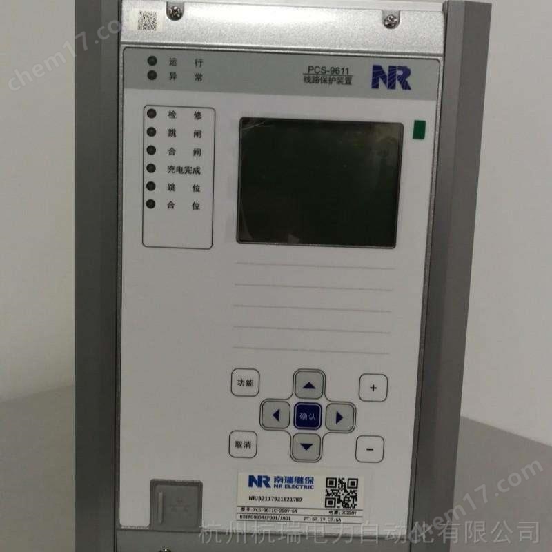


Nanjing NARI RCS9611CS microcomputer protection device
NegotiableUpdate on 05/14
- Model
- Nature of the Manufacturer
- Producers
- Product Category
- Place of Origin
Overview
If the Nanjing Nanrui RCS9611CS microcomputer protection device is installed in a group screen, the protection cabinet itself must be reliably grounded. There is a grounding copper bar inside the cabinet, which must be reliably connected to the grounding network of the power station. Where possible, shielded cables should be used, and the shielding layer should be grounded simultaneously in the switch field and control room. The current lines and neutral lines of each phase should be placed in the same cable.
Product Details
Nanjing NARI RCS9611CS microcomputer protection device
Abnormal device information and handling suggestions
serial numberAbnormal/self checking informationMeaningSuggestions for handling
1Fixed value errorThe content of the fixed value area has been damaged, and it is locked for protectionNotify the manufacturer to handle it
2power failureDC power supply abnormal, locked protectionNotify the manufacturer to handle it
3CPLD malfunctionCPLD chip damaged, locked protectionNotify the manufacturer to handle it
4PT disconnectionVoltage circuit disconnection, alarm signal sent, partial protection lockedCheck the wiring of the voltage secondary circuit
5CT disconnectionThe current circuit is disconnected, an alarm signal is sent, and the protection is not lockedCheck the wiring of the current secondary circuit
6TWJ abnormalityWhen the switch is in the jump position but there is current, it sends an alarm signal and does not lock the protectionCheck the auxiliary contacts of the switch
7frequency anomalyAlarm will be triggered when the system frequency is below 49.5hz, without locking protectionCheck the system once
8Grounding alarmThe system sends an alarm signal when the single-phase grounding zero sequence voltage exceeds the threshold value, without locking protectionCheck the system once
9Spring without energy storageThe spring operating mechanism generates an alarm signal when the energy storage is insufficient and exceeds the delay, without locking protectionCheck the operating mechanism
10CtrError ActThe device cannot detect either jumping or closing positions; The monitoring circuit for jumping or closing is disconnected and not locked for protection
Check the monitoring circuit
11Zero sequence alarmZero sequence current exceeds the set value, no lockout protection is providedCheck the zero sequence current
12Over-temperature alarmThe device detects high oil temperature and opens without locking the protectionCheck the system once
13Light gas alarmThe device detects the entry of light gas and does not lock the protectionCheck the system once
14Overload alarmLoad current exceeds the set value, without locking protectionCheck the load current
15Non electricity alarmThe device detects non electric input and does not lock the protectionCheck the system once
16Overvoltage alarmBus voltage exceeds the set value, without locking protectionCheck the system voltage
17Unbalanced current alarmUnbalanced current exceeds the set value, without locking protectionCheck the system once
18Switch refusal to moveAfter the device emits a trip pulse, the corresponding switch does not trip openCheck the switch operation circuit and auxiliary components
contact point
19Wrong balance coefficient (transformer)
Equipment)The balance coefficient on the Y side should be less than 2.3
The △ side balance coefficient should be less than 4. Balance coefficient interlock protectionIf the device reports' balance coefficient error ', it indicates that the balance coefficient is too large. Change the CT ratio to meet the requirements.
20Wrong wiring method (transformer)
Equipment)KMODE is not within the setting range (00~19), and the wiring method is incorrectly locked for protectionCheck the wiring method settings in the system settings
21CPU startup setting errorThe content of the starting fixed value area is damaged, the device alarms, and switches to the main CPU to control the starting relayNotify the manufacturer to handle it
22Starting CPU communication errorAbnormal communication between the startup CPU and the main CPUNotify the manufacturer to handle it
23Starting CPU power failureThe DC power supply of the starting CPU is abnormal, the device alarms, and the independent starting relay is lockedNotify the manufacturer to handle it
24Starting the CPU for a long timeThe differential current of the starting CPU exceeds the starting set value, causing a delay of 10 seconds and reporting that the starting CPU is starting for a long time. The device also sounds an alarmCheck if the differential current on the device exceeds the differential starting value, or exceeds the overcurrent setting on the three or four sides, and investigate the corresponding cause.
25Instantaneous CT disconnectionDevice alarmThe device alarm remains on and the alarm light does not turn off until the "confirm" button on the panel is pressed or there is a signal to reset the switch in or remotely reset. Check the wiring of the current secondary circuit
26Zero sequence overvoltage alarmThe system generates an alarm signal when the single-phase grounding zero sequence overvoltage exceeds the threshold value, without locking protectionCheck the system once
27overheat alarmThe percentage of overheating alarm input and heat accumulation greater than the overheating protection setting valueCheck the system once
Nanjing NARI RCS9611CS microcomputer protection device
1.1 Scope of Application
RCS-9611CS is suitable for line protection and measurement devices in non directly grounded systems or low resistance grounded systems with voltage levels below 110kV. It can be installed in groups or on-site in switchgear.
1.2 Protection configuration and functionality
1) Three stage overcurrent protection that can withstand overvoltage and directional locking.
2) Three stage zero sequence overcurrent protection.
3) Overcurrent acceleration protection and zero sequence acceleration protection (zero sequence current can be self generated or externally added).
4) Overload function (alarm or trip).
5) Low cycle load reduction function.
6) A section of low voltage protection.
7) A section of busbar overvoltage protection.
8) A section of zero sequence overvoltage protection.
9) A period of high week protection.
10) Overcurrent lockout.
11) Three phase one-time reclosing.
12) Low current grounding line selection function (must use external zero sequence current).
13) Independent operating circuit.
2. Working principle of software
2.1 Overcurrent protection
This device is equipped with three stages of overcurrent protection, each with independent current and time settings as well as control words. Each section can independently choose whether to be locked by overvoltage (negative sequence voltage and low voltage) or directional locking.
The sensitivity angle of the directional component is 45 degrees, and a 90 degree wiring method is used. The directional element and the current element are connected in a phase based starting mode. The directional component has a memory function, which can eliminate the dead zone of the directional component when there is a three-phase short circuit nearby.
When the bus PT is disconnected, the control word "PT disconnection current protection" can be used to select whether to exit the complex voltage interlock and direction interlock of the current protection in this section to become pure overcurrent protection, or to directly exit the current protection. The "current protection" referred to here refers to the current protection sections that have been locked with compound voltage or directional locking. The current protection section that does not have either overvoltage or directional locking is not affected by this control word.
The overcurrent section I and overcurrent section II are fixed as timed protection; The overcurrent section III can be selected by a control word to determine whether it is a definite time or inverse time. The inverse time characteristic follows the provisions of the International Electrotechnical Commission (IEC255-4) and the British Standard Specification (BS142.1996), and the following three standard characteristic equations are used for selection.
Similar Product Recommend