-
E-mail
2822343332@qq.com
-
Phone
15810615463
-
Address
Mapo Xiangyue Sijisan District, Shunyi District, Beijing
Product Categories
Beijing Jingke Zhichuang Technology Development Co., Ltd


KZC-CC500E+Type Right Angle Ruler Inspection Instrument
NegotiableUpdate on 01/05
- Model
- Nature of the Manufacturer
- Producers
- Product Category
- Place of Origin
Overview
This instrument is an excellent new precision testing device in China, equipped with a computer and a ruler calibration software that can collect, process, store, and print out test data. It is currently a computer-controlled ruler inspection instrument.
Product Details
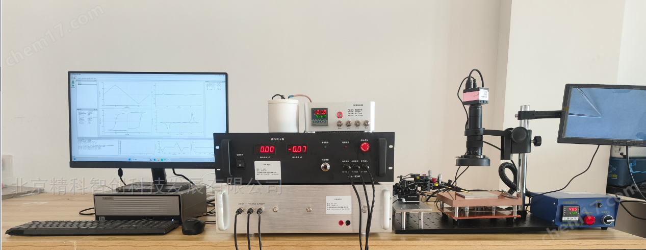
JKZC-CC500E+typeRight angle ruler inspection instrumentPhoto:

Xi'an Qing'an Group---Ministry of Aerospace108 institutions

第5713 Factory - Nationalpreventmeasurement station
JKZC-CC500E+Technical Agreement for Type Right Angle Ruler Inspection Instrument
Instrument function
This instrument is an excellent new precision testing device in China, equipped with a computer and a ruler calibration software that can collect, process, store, and print out test data. It is currently a computer-controlled ruler inspection instrument.
1. Check the verticality of various types of square rulers (inner and outer corners) with dimensions up to 500mm, ranging from 0 to 2 levels;
2. Check the perpendicularity of each working surface and V-groove of the frame level of various specifications up to 300 × 300mm to the zero position (bar level) of the horizontal bubble;
3. Check the perpendicularity of each working surface and V-groove of the 200 × 200mm square box;
4. Detect the verticality of mechanical parts with high accuracy;
OneMain technical parameters
Measurement range: 0-500MM
Probe resolution: 0. 2μm
The straightness of the workbench: 2.0μm / 750×138 mm
indication variability: ±0.4Mm
indication error: ± (0.3+L/300) μ m (L is the measured length in millimeters)
volume 750×138×750mm3
weight 40kg
IIJKZC-CC500E+Description of Verification Software for Type Right Angle Ruler Inspection Instrument
Right angle ruler calibration software1.0
1System Introduction
Right angle ruler calibration software 1.0》(hereinafter referred to asVerification software "is applicable to newly manufactured, repaired, and
Verify the square ruler in use and generate a verification report.
This verification software is a subsystem of the metrological verification software system developed by our company.
Verification regulations:JJG 7-2004Verification Regulations for Square Rulers
Operating environment:Windows9xIf the above operating systems need to output calibration reports, a printer is also required.
The main interface of the verification software during operation is shown in the following figure:

2. Verification
2.1 Verification information input
In the main interface of the verification software, enter the verification information separately: verified instrument, basic verification information, calibrator
Records and certificates, metrology personnel, etc.
Users can directly input the corresponding information in the input box, and unnecessary information does not need to be entered.
2.2 Verification data input
As shown in the following figure, directly in the calibration tableEnter the corresponding calibration data in the "Calibration Data" column,
After inputting the verification data, the conclusion column will display the verification conclusion of the project (for different verification objects,
This table may have differences. The inspection data in the appearance quality column refers to the description of the appearance, and the conclusion needs to
artificial selection'Qualified' or 'unqualified'.

For the verification of verticality, you can directly enter the verticality value in the verification data column, or click on the right side of the column
Edge buttonThe program will pop up a dialog box for verticality verification, as shown in the following figure
Show:

The instrument display column will show the measurement value of the measuring head in the current position status. If the measuring instrument is not connected to the computer
The machine and instrument display columns will not be displayed.
After the probe moves to the calibration position, press the button on the right side of the columnRead button, the program will display the current measurement data
Read into the table, or directly enter data in this column.
After the verification is completed, pressThe 'OK' button completes the verification.
3Report
3.1 Create Report
After all inspections are completed, executeThe "Create Report" command in the "Report" menu will bring up the following image
The dialog box shown prompts the user to select a template for creating a report (the creation and design of this template are determined byMeasurement
verification”The software is completed, please refer to the relevant information of the "Metrology Verification" software. Click the "OK" button, and the program will
Create a report based on the template selected by the user.
3.2 Save report
executeThe "Save" command in the "File" menu will prompt the user to open a file save dialog box
Save the report in the designated location.
3.3 print report
executeThe 'Print' command in the 'File' menu allows you to print the report.
3.4 View Report
executeThe "Open" command in the "File" menu will bring up an open dialog box, where you can select the report file
After opening, you can view or print the report.
Similar Product Recommend