-
E-mail
jscyxyb@hotmail.com
-
Phone
17361727761
-
Address
No. 258 Zhanxi Road, Jiangyin City, Jiangsu Province
Product Categories
Jiangsu Chenyuxin Instrument Co., Ltd

Instruction manual for gas steam flowmeter
NegotiableUpdate on 04/21
- Model
- Nature of the Manufacturer
- Producers
- Product Category
- Place of Origin
Overview
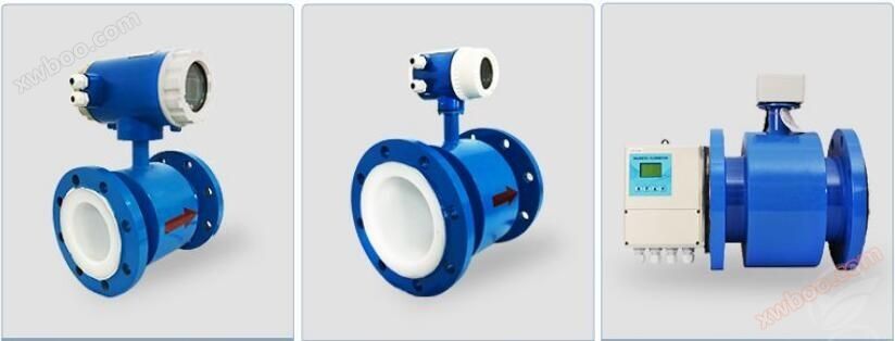
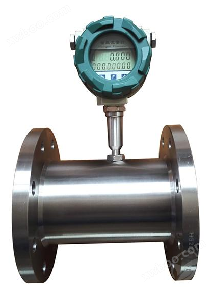
The gas steam flowmeter is composed of a turbine flow sensor and a display instrument. It is manufactured by our factory using advanced foreign technology and is one of the most ideal flowmeters for liquid flow. Flow meters have the characteristics of simple structure, high accuracy, and easy installation, maintenance, and use. This product is widely used in the fields of petrochemicals, metallurgy, water supply, papermaking, environmental protection, food, etc. It is suitable for measuring liquids in closed pipelines that do not corrode stainless steel 1Cr18Ni9Ti, 2Cr13, corundum Al203, hard alloys, and have no impurities such as fibers or particles. If used in conjunction with display instruments with special functions, it can be used for automatic quantitative control, over limit alarm, and other purposes;
Product Details
The gas steam flowmeter is composed of a turbine flow sensor and a display instrument. It is manufactured by our factory using advanced foreign technology and is one of the most ideal flowmeters for liquid flow. Flow meters have the characteristics of simple structure, high accuracy, and easy installation, maintenance, and use. This product is widely used in the fields of petrochemicals, metallurgy, water supply, papermaking, environmental protection, food, etc. It is suitable for measuring liquids in closed pipelines that do not corrode stainless steel 1Cr18Ni9Ti, 2Cr13, corundum Al203, hard alloys, and have no impurities such as fibers or particles. If used in conjunction with display instruments with special functions, it can be used for automatic quantitative control, over limit alarm, and other purposes;
Characteristics of gas steam flowmeter:
The sensor is a hard alloy bearing thrust type, which not only ensures accuracy but also improves wear resistance. The structure is simple, sturdy, and easy to disassemble and assemble; Wide measurement range, low lower limit flow rate; Small pressure loss, good repeatability, high precision, and the impeller has anti-corrosion function; Has high resistance to electromagnetic interference and vibration;
Working principle:
The fluid flows through the sensor housing. Due to the angle between the blades of the impeller and the flow direction, the impulse of the fluid causes the blades to have a rotational torque. After overcoming the friction torque and fluid resistance, the blades rotate. After the torque is balanced, the speed is stable. Under certain conditions, the speed is proportional to the flow velocity. Due to the magnetic conductivity of the blades, they are in the magnetic field of the signal detector (composed of permanent magnet and coil). The rotating blades cut the magnetic field lines and periodically change the magnetic flux of the coil, thereby inducing electrical pulse signals at both ends of the coil. This signal is amplified and shaped by the amplifier
Calculation of gas steam flowmeter
Form a continuous rectangular pulse wave with a certain amplitude, which can be transmitted remotely to the display instrument to display the instantaneous flow rate and cumulative amount of the fluid. Within a certain flow range, the pulse frequency f is proportional to the instantaneous flow rate Q of the fluid flowing through the sensor. The flow equation is Q=3600 × f/k, where:
F - Pulse frequency [Hz]; K - Instrument coefficient of the sensor
Q - instantaneous flow rate of fluid (in working condition) [m3/h];
3600- Conversion factor; The instrument coefficient of each sensor is filled in the calibration certificate by the manufacturer, and the k value is set in the matching display instrument to display the instantaneous flow rate and cumulative total amount;
Main technical performance:
Nominal diameter: DN4-DN200mm
Medium temperature: (-20-80) ℃, (-20-120) ℃, (-20-150) ℃; Oral environment temperature: (-20-55) ℃;
Accuracy level: ± 0.2%, ± 0.5%, ± 1%; Output signal: voltage pulse, 4-20mA two-wire system;
Power supply: Sensor:+5V~+24VDC (external)
Transmitter:+24VDC (external), flow meter: 3.0V lithium battery (built-in)
Display mode: On site display, high-definition LCD display simultaneously displays instantaneous flow (4 significant digits) and cumulative flow (8 significant digits, with reset function). All valid data remains intact for 10 years after power failure.
Body material: 304, 316L;
Impeller material: 2Cr13 (titanium plated, dual phase steel) Bearing material: hard alloy;
Connection methods: thread, flange, flange clamp, sanitary clamp interface;
Flange standard: National standard
Work pressure: 1.6~42MPa (10-42MPa high pressure requires customized processing);
Protection level: lP65; Explosion proof grade: ExdllCT6Gb;
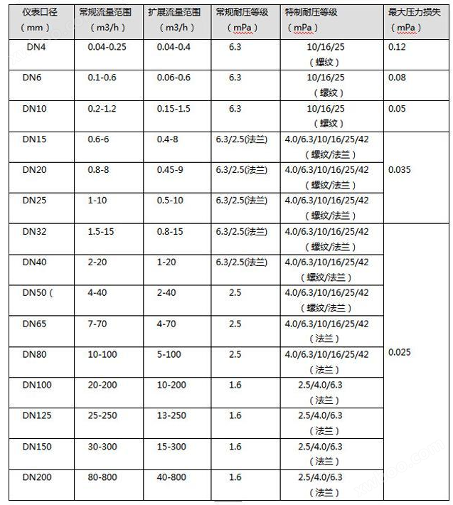
Flow range and working pressure:
Installation size:
The installation method of the sensor adopts threaded or flange connection according to different specifications. The installation method is shown in the figure
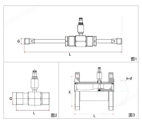
Figure 1DN4-DN10 threaded connection and flange connection (including straight pipe section)
Figure 2DN15-DN50 threaded connection
Figure 3DN15-DN200 flange connection
Similar Product Recommend