- Phone
-
Address
Chongnan Road Lane, Xiaokunshan Town, Songshan District, Shanghai
Product Categories
Shanghai Bihu Pump Manufacturing Co., Ltd

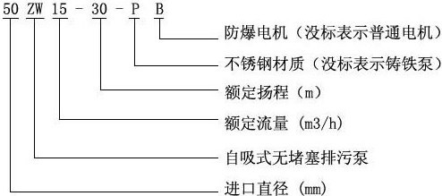
ZWP explosion-proof stainless steel self-priming sewage pump
NegotiableUpdate on 05/13
- Model
- Nature of the Manufacturer
- Producers
- Product Category
- Place of Origin
Overview
Compared with similar domestic products, the ZW type non clogging self-priming sewage pump has the characteristics of simple structure, good self-priming performance, strong sewage discharge capacity, high efficiency and energy saving, and easy use and maintenance.
Product Details
ZW type stainless steel self-priming sewage pump Product introduction:
ZW type unobstructed self-priming sewage pump, also known as solid-liquid pump or impurity pump. It integrates the functions of a self-priming pump and a non clogging sewage pump, using an axial reflux external mixing type with hydraulic design. The impeller is enclosed in a separate impeller chamber, connected to a pressurized water chamber. When the impeller rotates, the liquid in the pump generates a strong axial vortex effect, creating a vacuum at the inlet and a head at the outlet. Therefore, impurities can be discharged from the pressure chamber, so its flow channel is unobstructed, and its discharge effect is the same as other self-priming discharge pumps. Through the design of the pump body and impeller flow channel, it is possible to suction and discharge liquids containing large solid particles and long fiber impurities without the need for bottom valves and inlet water like a typical self-priming centrifugal pump.
ZW type stainless steel self-priming sewage pump model meaning:
[ZW type stainless steel self-priming sewage pump] Product advantages:
Compared with similar domestic products, the ZW type non clogging self-priming sewage pump has the characteristics of simple structure, good self-priming performance, strong sewage discharge capacity, high efficiency and energy saving, and easy use and maintenance.
The ZW type unobstructed self-priming sewage pump belongs to the domestic * in the sewage pump series products. All technical performance indicators are at a good level in China, with broad application markets and development prospects.
[ZW type unobstructed self-priming sewage pump] Product use:
ZW type non clogging self-priming sewage pump can be used without installing a bottom valve like a general self-priming water pump, and can also suck and discharge engineering wastewater containing large solid particles, long fibers, sediments, waste impurities, feces treatment, and all other materials. It can be widely applied to industries such as municipal sewage engineering, light industry, papermaking, textile, food, chemical industry, electric power, petroleum, mining, and river pond aquaculture. It is currently an impurity pump for pumping solid particles, fibers, slurries, and mixed suspensions in China.
Structural diagram of ZW type unobstructed self-priming sewage pump:
|
1 |
import flange |
2 |
slap the door |
|
3 |
Add liquid bolt |
|
4 |
outlet flange |
|
5 |
pump body |
|
6 |
Gas-liquid separation tube |
|
7 |
back cover |
|
8 |
impeller |
|
9 |
mechanical seal |
|
10 |
pump shaft |
|
11 |
Front bearing |
|
12 |
bearing housing |
|
13 |
rear bearing |
|
14 |
Coupling |

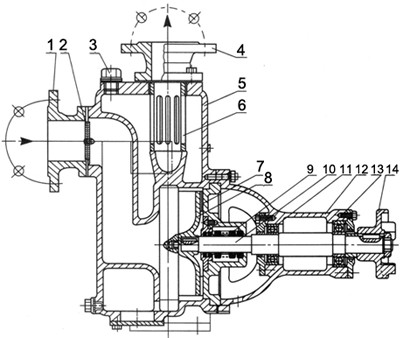
ZW type unobstructedSelf suction sewage pumpIt is a single-stage single suction horizontal type, with an axial suction inlet and a vertical upward discharge outlet. When viewed from the suction inlet towards the motor end, it rotates clockwise.
Pump inlet and outlet connection: The basic type is flange (GB115.7-8-88). The supporting motor is a Y-shaped asynchronous motor, which can be selected from ordinary or explosion-proof types, and can be negotiated separately according to requirements. The body material of ZW self-priming sewage pump is HT200, and the impeller material is QT400-18. Stainless steel can also be selected according to user needs for conveying corrosive media.
ZW type unobstructed self-priming sewage pump performance parameters:
model |
import and export caliber (mm) |
traffic (m3/h) |
head (m) |
Motor power (kw) |
Self suction height (m) |
25ZW8-15 |
25×25 |
8 |
15 |
1.5-2P |
5 |
32ZW10-20 |
32×32 |
10 |
20 |
2.2-2P |
|
40ZW20-15 |
40×40 |
20 |
15 |
2.2-2P |
|
40ZW15-30 |
15 |
30 |
3.0-2P |
||
50ZW10-20 |
50×40 |
10 |
20 |
2.2-2P |
|
50ZW20-15 |
20 |
15 |
2.2-2P |
||
50ZW18-22 |
18 |
22 |
3.0-2P |
||
50ZW15-30 |
15 |
30 |
3.0-2P |
||
65ZW30-18 |
65×50 |
30 |
18 |
4.0-2P |
|
65ZW20-30 |
20 |
30 |
5.5-2P |
||
65ZW25-40 |
25 |
40 |
7.5-2P |
||
80ZW40-16 |
80×65 |
40 |
16 |
4.0-4P |
|
80ZW65-25 |
65 |
25 |
7.5-2P |
||
80ZW80-35 |
80 |
35 |
15.0-2P |
||
80ZW50-60 |
50 |
60 |
22.0-2P |
||
80ZW80-45 |
80 |
45 |
22.0-2P |
||
100ZW80-20 |
100×80 |
80 |
20 |
7.5-4P |
|
100ZW100-15 |
100 |
15 |
7.5-4P |
||
100ZW100-20 |
100 |
20 |
11.0-4P |
||
100ZW100-30 |
100 |
30 |
22.0-2P |
||
100ZW80-45 |
80 |
45 |
30.0-2P |
||
100ZW80-60 |
80 |
60 |
37.0-2P |
||
100ZW80-80 |
80 |
80 |
45.0-2P |
||
125ZW120-20 |
125×125 |
120 |
20 |
15.0-4P |
|
150ZW200-15 |
150×150 |
200 |
15 |
15.0-4P |
|
150ZW200-20 |
200 |
20 |
22.0-4P |
||
150ZW200-28 |
200 |
28 |
30.0-4P |
||
150ZW400-25 |
400 |
25 |
55.0-2P |
||
150ZW180-40 |
180 |
40 |
55.0-4P |
||
200ZW280-12 |
200×150 |
280 |
12 |
22.0-4P |
|
200ZW300-18 |
300 |
18 |
37.0-4P |
||
200ZW300-25 |
300 |
25 |
45.0-4P |
||
200ZW280-28 |
280 |
28 |
55.0-4P |
||
250ZW400-22 |
250×200 |
400 |
22 |
55.0-4P |
|
300ZW800-14 |
300×250 |
800 |
14 |
55.0-4P |
Installation diagram of ZW type unobstructed self-priming sewage pump:
|
1 |
pump |
2 |
pressure gauge |
|
3 |
Export vertical pipe |
|
4 |
Inhalation of hard throat |
|
5 |
elbow |
|
6 |
flow control valve |
|
7 |
Export pipeline |
|
8 |
Add liquid plug |
|
9 |
vacuum gauge |


ZW type unobstructedSelf suction sewage pumpThe quality of installation has a significant impact on the operation and lifespan of the pump, so it must be carried out carefully. (Refer to the schematic diagram for the installation of standardized pump pipelines)
1. The installation height of the suction inlet of ZW type unobstructed self-priming sewage pump should not exceed 5 meters as much as possible, and special attention should be paid to the sealing of the suction pipeline to avoid air leakage and affect the self-priming capacity and normal operation of the pump.
2. The outlet of the ZW type unobstructed self-priming sewage pump should first be equipped with a vertical pipe (usually 0.4-1 meters) and a pressure gauge, and then the outlet flow control valve and other pipelines should be installed.
3. Reasonably configure the length and diameter of the pump inlet and outlet pipelines to reduce unnecessary head loss along the way. (Reference can be made to the straight pipe friction loss summary table for estimation)
4. When transporting over long distances, larger pipe diameters should be selected. The pump pipeline should have its own support, and the pump body itself is not allowed to bear the load of the pipeline.
5. If a check valve is installed in the discharge pipeline, it should be installed outside the outlet flow control valve.
Similar Product Recommend


