-
E-mail
18612919058@163.com
-
Phone
18612919058
-
Address
No. 86 Wanxing Road, Changyang, Fangshan District, Beijing
Product Categories
- Dielectric strength tester
- Breakdown voltage testing machine
- Cheng Kong Ultra High Voltage Tester
- Voltage breakdown tester
- Surface resistivity tester
- Insulation material volume resistivity tester
- Differential scanning calorimeter
- Carbon black content tester
- Touch screen voltage breakdown tester
- Insulation oil chromatograph
- Dielectric breakdown strength tester
Beijing Zongheng Jinding Instrument Equipment Co., Ltd
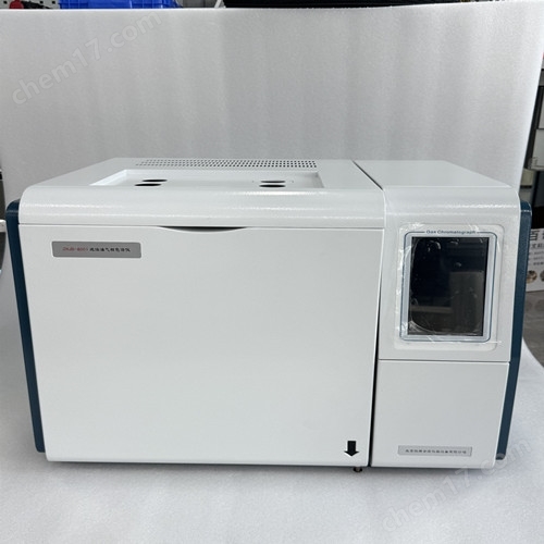
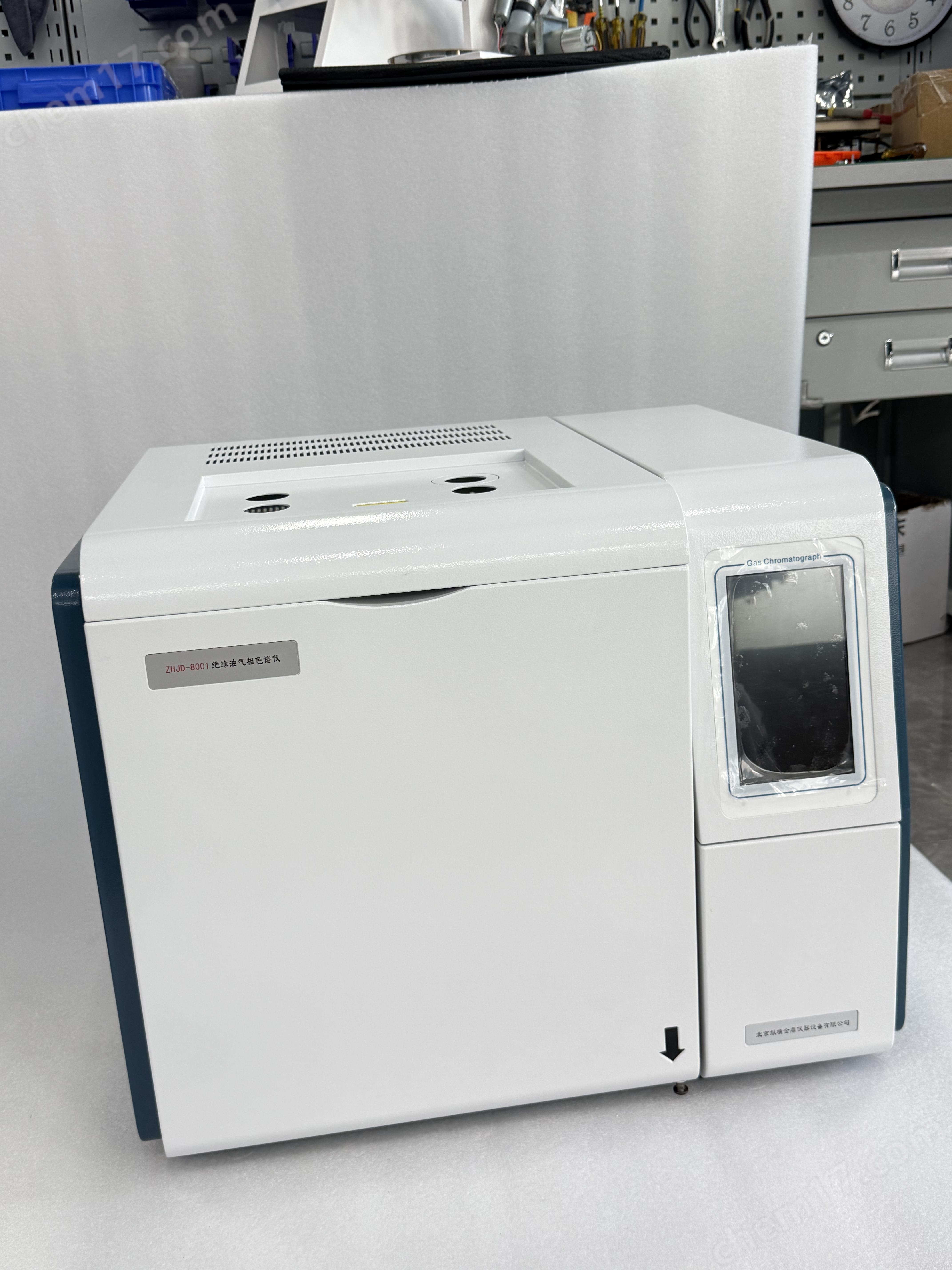

Transformer oil and gas chromatograph
NegotiableUpdate on 01/12
- Model
- Nature of the Manufacturer
- Producers
- Product Category
- Place of Origin
Overview
The transformer oil and gas chromatograph consists of an injector, detector, chromatographic column box, gas flow control system, circuit control detection system, and optional dedicated workstation. Optional detectors such as FID, TCD, ECD, FPD, etc. It can be widely used for quality control and product testing in chemical, pharmaceutical, food and other fields. $r $n $r $n 1.3.1 Main technical indicators: $r $n ● Operation display: 192 * 64 dot matrix sinicization solution ● Temperature control area: 6 channels $r $n ● Temperature control range: room temperature+5 ℃~400 ℃, increment: 1 ℃, accuracy: #177; 0.1℃
Product Details
High pressure hazarddanger:
●It is strictly prohibited to remove the instrument cover during operation. During the operation of the instrument, the interior of the instrument may cause personal injury
The presence of high voltage can cause damage, and when disassembling the instrument cover, it may expose some electrical components.
●When replacing fuses and disassembling and maintaining instruments, the power plug should be unplugged first. Turning off the power switch of the instrument is just
Stop the instrument operation, as the high voltage has not been completely cut off at this time.
●If the power cord is worn or damaged, it must be replaced immediately.Transformer oil and gas chromatograph
High temperature dangerdanger:
●During the operation or shutdown of the instrument, there may be a certain temperature in the parts such as the injector, detector, column box, and rear air outlet, which should be avoided from contact to prevent burns. If parts need to be replaced, be sure to wait until the instrument temperature drops to room temperature or use appropriate protective measures before proceeding!
●Pay attention to the hot gases emitted during instrument cooling to prevent burns;
●Flammable materials should not be placed behind the instrument to prevent the release of hot gases from igniting flammable materials!
●The gas source pipeline should avoid the rear air outlet of the instrument to prevent the hot gas discharged from melting the gas source pipeline and causing further damage
Great danger!
Gas source hazarddanger:
●For the gas cylinders and sources used in the instrument, relevant regulations on gas cylinder transportation, storage, management, and safe use should be followed.
●When using hydrogen as a carrier gasorFIDWhen using gas, it is important to be aware that hydrogen gas may leak into the column box and pose a risk of explosion. So before connecting the pipeline, it is necessary to turn off the gas source, install the chromatography column, connect the connectors of the injector and detector, and perform leak detection on all connecting pipelines and valves before opening the hydrogen gas source. To prevent hydrogen gas from leaking into the column box and causing danger.
●When conducting special sample analysis (such as toxic) or when the instrument may release toxic substances, the instrument's discharge should be placed in a safe outdoor location to prevent indoor pollution or even poisoning.
Transformer oil and gas chromatograph
Welcome to become a user of gas chromatography!
1.1 Working principle of gas chromatograph
Gas chromatography analysis technology is a technique for separating and analyzing multi-component mixtures. It mainly utilizes the differences in boiling point, polarity, and adsorption coefficient of each component in the sample in the chromatographic column to separate each component in the column, and performs qualitative and quantitative analysis on the separated components.
Gas chromatography uses gas as the mobile phase (carrier gas). When the sample is sent into the injector and vaporized, it is carried by the carrier gas into the packed column or capillary column. Due to the differences in boiling point, polarity, and adsorption coefficient of each component in the sample, the components are separated in the column. Then, the detector connected to the column detects each component in order based on its physical and chemical properties. Finally, the converted electrical signal is sent to the chromatography workstation, which records and analyzes the gas chromatogram of each component to obtain the analysis results of each component. The working principle diagram is shown in the following figure:

Schematic diagram of the working principle of gas chromatograph
Due to its high separation efficiency, fast analysis speed, and low sample usage, this analysis method has been widely used in various sectors such as petrochemicals, biochemistry, medicine and health, health quarantine, food inspection, environmental protection, food industry, and medical clinical practice. Gas chromatography has effectively solved problems such as quality inspection, scientific research, pollution detection, and production control of intermediates and industrial products in these fields.
1.2 Characteristics of Series Chromatography Instruments
The company utilizes its strong technological development capabilities, adopting a brand new industrial design, electronic circuits, and integrating them into today's marketofIPTechnology applied to gas chromatography. The instrument adopts new highly integrated industrial grade chips, bus technology, Ethernet, and data processing technology, optimizing temperature control programs and gas path control, fundamentally improving the reliability and maintainability of the instrument.
Series gas chromatographThere are the following functions and features (some functions require the selection of a dedicated workstation):
★ Adopting advanced technologyof10/100MAdaptive Ethernet communication interface, in parallelplaceIPProtocol stackThe instrument can easily realize long-distance data transmission through the enterprise's internal LAN and Internet; Facilitating the setup of the laboratory, simplifying the configuration of the laboratory, and facilitating the management of analytical data.
★ instrumentInternal setupplan3An independent connection process that can connect to local processing (laboratory site), unit supervisors (such as quality inspection department heads, production plant managers, etc.), and higher-level supervisors (such as environmental protection bureaus, technical supervision bureaus, etc.), making it convenient for unit supervisors and higher-level supervisors to monitor the operation of instruments and analyze data results in real time.
★ Instrument selectionofNetChromTMThe workstation can support multiple chromatography instruments simultaneously, enabling data processing and control, simplifying document management, andGreatly reduces users' laboratory investment and operating costs.
★ systemEquipped with both Chinese and English operating systems, users can switch between them as needed.
★ Temperature controlled areaUsers can freely name it for convenient use.
★ ceremonyThe instrument adopts a multi processor parallel working mode, making it more stable and reliable;canSatisfy complex sample analysis, capable ofMultiple options availableA high-performance detector,asFIDTheTCDTheECD、andFPD, can be installed at most simultaneouslyfourDetector. Additional detectors can also be used, which is very convenient after purchasing the instrumentlandselect、Install other detectors.
★ ceremonyThe device adopts a modular structure, with clear design and easy replacement and upgrade, which protects the effectiveness of investment.
★ The brand new microcomputer temperature control system has high temperature control accuracy, reliability, and anti-interference performance; Equipped with a six channel fully independent temperature control system, it can achieve sixteen step programmed heating,Enable the device to handle a wider range of sample analysisEquipped with a column box automatic rear door opening system, the precision of low-temperature control is improved,rise/The cooling rate is faster.
★ Instruments can be optionally selectedadvancedelectronflow controller(EFC)、Electronic pressurecontroller(EPC)By implementing digital control, the reproducibility of qualitative and quantitative results can be greatly improved.
★ The instrument is designed with a timed self starting program, which can easily complete online analysis of gas samples (requiring online automatic injection components).
★ The operating system of the fully microcomputer controlled keyboard is simple and convenient to operate; And design detector automatic recognition technology. It has the functions of fault diagnosis and power-off data protection, and can automatically memorize set parameters.
★ The instrument is built-in with low noise and high resolutionrate24bitADThe circuit has the functions of baseline storage and baseline deduction.
★ Collecting chromatographic signals and data processing, suitable forYuWinXPTheWin2000TheWindows7Waiting for the operating system. By Fu
combine, synthesizeA/A(American Analytical Society) StandardofCDFRead the sampling data into the file,becauseThis canandAgilentTheWaters
Waiting for the chromatographic workstation to be connected.
★ Chromatography system with independent intellectual property rights, equipped withhaveMODBUS/TCPThe standard interface canandDCS
Convenient docking.
★ The instrument can be integrated with automatic samplers produced by multiple manufacturers both domestically and internationally; Like ShimazuofAOC-20iYi DabenefitHTAcompanyofHTSeries of high-efficiency liquid and gas automatic samplers, etc.
1.3 Series gas chromatographoftechnical indicators
The gas chromatograph consists of an injector, detector, chromatographic column box, gas flow control system, circuit control detection system, and optional dedicated workstation. optionalmatchFIDTheTCDTheECDTheFPDWaiting for the detector. Widely applicableApplied to quality control in chemical, pharmaceutical, food and other fieldsProduct testing.
1. 3.1Main technical indicators:
●Operation display:192*64Dot matrix Sinicized Liquid Crystal
●temperature controlregion:6road
●Temperature control range: room temperature+5℃~400℃, incremental:1℃, precision:±0.1℃
●Program heating order:16step
●Cheng Sheng rate:0.1~40℃/min
●Pneumatic controlMechanical valve control mode and electronic pressure flow control mode are optional
●external event:4road
●Type of sampler: Fill column, capillary tubeSix way valve gas injection、Automatic headspace injectionWaiting for selection
●Number of detectors:4One;FIDTheTCDTheECDTheFPD(Optional)
●Start injection: Choose between manual and automatic options
●Communication interface:Ethernet:IEEE802.3
1.3.2 Technical specifications of detector
Hydrogen flame ionization detector(FID)
●detection limit:≤2×10-11g/s (Hexadecane)/isooctane);
●Baseline noisesound:≤5×10-14A
●baseline drift:≤1×10-13A/30min
●linear range: ≥106
thermal conductivity detector(TCD)
●sensitivity:S≥2500mV•ml/mg(benzene/toluene)(putbig1、2、4、8Multiple Choice)
●Baseline noise:≤20MV
●baseline drift:≤30MV/30min
●linear range: ≥104
Electronic capture detectiondevice(ECD)
●detection limit:≤1×10-13g/ml(C body 66)six/Isooctane)
●Baseline noisesound:≤0.03mV
●baseline drift:≤0.2mV/30min
●linear range:103
●Radioactive Source:63Ni
Flame photometric detectiondevice(FPD)
●detection limit:(S)≤5×10-11g/s The(P)≤1×10-12g/s;/Anhydrous ethanol)
●Baseline noisesound:≤3×10-13A
●baseline drift:≤2×10-12A/30min
●linear range: Regarding sulfur≥102Regarding phosphorus≥103
1.4 Main Configuration Description
1.4.1.1 Overview of Gas Flow Control System
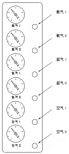
*****The gas path control system of the gas chromatograph can be configured as follows:
☆ Mechanical valve, pointer pressure gauge pneumatic system;
☆ Mechanical valve, electronic pressure and flow pneumatic system (optional);
☆ Partial mechanical valves, partial electronic pressure and flow control pneumatic system (optional);
☆ Fully electronic pressure and flow control pneumatic system (optional)
Carrier airflow path:
The carrier gas passes through the pipeline filter and is provided with a stable input air pressure by the upstream stabilizing valve (adjusted at the factory)about0.35MPa)Divided into dual gas paths through three-way connections, one path supplies pressure protection components to achieve system protection after gas interruption; The other carrier gas passes through the stabilizing valve separately(orEPCTheEFCModule) adjusts the flow rate of the carrier gas and enters the samplerⅠTheⅡ.
Hydrogen flow path:
Hydrogen gas passes through a pipeline filter and is divided into two gas paths through a three-way valve. The hydrogen gas in each path passes through a pressure regulator valve(orEPCTheEFCAdjust the hydrogen flow rate using a module and an air resistance. If a capillary column is used and combined with tail gas (carrier gas), then enter the detector separately.
Air flow path:
 The air passes through a pipeline filter and is divided into dual air paths through a three-way valve. The dual air paths pass through pressure regulating valves respectively(orEPCTheEFCModule) and air resistance regulate the flow and enter the detector.
The instrument flowchart is shown in the diagram on the right:
policeannounce1: The initial pressure regulator valve for the carrier gas (inside the host) has undergone strict debugging before leaving the factory. Do not change the output pressure of the gas path pressure regulator valve on your own to avoid affecting the control output accuracy!
policeannounce2: When closing the knobs of the pressure regulating valve, flow regulating valve, and needle valve, it is not advisable to turn them all the way to avoid damaging the valve components!!
1.4.1.2 Electronic gas pressure and flow measurement system (Optional)
When using mechanical valves (steady flow valves, pressure regulating valves) for gas flow and pressure control, traditional pressure gauge measurement methods can be used, or electronic gas pressure and flow measurement systems can be used, which can display the gas flow rate in real time and are convenient to use.
When using an optional fully electronic gas pressure and flow measurement system, electronic gas pressure and flow measurement modules need to be configured. This module adopts high-quality pressure sensors, flow sensors, and high-resolution digital circuit design and manufacturing with temperature compensation, which has accurate measurement and stable performance. At the same time, it integrates multiple gas pressures internally力--The flow calculation algorithm (capillary gas control) can make the instrument pressure and flow rate clear at a glance.
1.4.1.3 EPCTheEFCcontrol system(Optional)
EPCTheEFCThe control system is a gas micro flow control system designed and manufactured using high-precision proportional valves, pressure sensors, and flow sensors. Compared with traditional mechanical valve control methods, it greatly improves the accuracy of gas pressure and flow control, enhances the automation level of instruments, eliminates the shortcomings of traditional mechanical valves that cannot compensate for temperature, and thus improves the overall performance of instruments.
Can be equipped with single or triple channelsroadEPCTheEFCControl module. The instrument can be equipped with up toplace24Road gas pressure and flow control.
EPCTheEFCAll operations of the control module are implemented on the instrument keyboard or optional dedicated workstation.
1.4.2 Chromatographic column box
PS-8001The column box of a gas chromatograph has a large volume, making it easy to install packed columns or capillary columns; Equipped with a built-in high-power heating wire and a rear opening door structure, it enablesrise/The cooling rate has been greatly improved; The temperature control protection of the column box adopts dual protection (see keyboard settings section) to ensure the safety of the chromatographic column; The heating wire of the column box is hidden behind the mesh plate to avoid peak splitting of the elastic quartz capillary column caused by thermal radiation.
The column box adopts low-noise motors and high-quality stainless steel fan blades to accelerate the temperature balance inside the column box. The instrument runs smoothly and the machine vibration is small.
PS-8001gas chromatographThe injector is installed on the top left front side of the column box, and its structure is shown in the following figure. Set and control its temperature by a microcomputer controller. The top of the injector is a heat dissipation cap, and the lower part of the heat dissipation cap is embedded with a silicone rubber injection pad. The carrier gas inlet of the sampler is connected to the output port of the steady flow valve in the pneumatic control system.

*****Schematic diagram of the structure of the gas chromatograph packed column sampler
Note:1.*****gas chromatographMultiple injectors can be equipped and multiple packed chromatography columns can be installed simultaneously.
2. *****gas chromatographThe sampler can be directly installed with an outer diameterforΦ3TheΦ4mmThe filling column.
3. *****gas chromatographThe injector can also be assembled into a non split injector by installing a non split liner,
like thischromatographThe sampler can be installed with stainless steel, glass, or flexible quartz glass capillaries of various diameters
Pipe column.
4. *****gas chromatographA dedicated capillary membrane can be installed to blow and divert the sample injector to achieve capillary action
divideflow/No diversion injection. As shown in the following figure.

*****Schematic diagram of capillary sampler structure for gas chromatograph
Note:From the schematic diagram, it can be seen that the capillary injector has an additional bypass gas path compared to the packed column injector, while the other structures are roughly similar
Similarly, the packed column sampler also has a diaphragm blowing function.
1.4.4 thermal conductivitypooldetector(TCD)
****gas chromatographCan be equipped with a thermal conductivity detector(TCD).TCDThe detector structure is shown in the following figure.
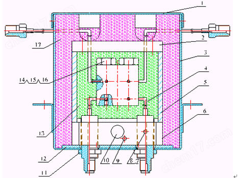
1 shellcover 2 upcover3 TCDbox4 TCDdetectiondevice 5 thermal conductionbody 6 bottomseat 7 snailnail 8 presspiece 9 Temperature sensing element
10 heaterdocument 11 snailmother 12 asbestos gasketpiece 13 poolbody 14 snailmother 15 cushioncircle 16 Thermin Yuandocument 17 thermal insulation cotton
TCDSchematic diagram of detector structure
Its structure and working principle are as follows: process four symmetrical chambers in a thermal conductor, and place one thermal sensor in each chamber. Among them, two chambers are measuring cells, and the other two are reference cells. The four arms of the Wheatstone bridge are composed of the thermistor elements in the measuring cell and the reference cell. The bridge is connected to the signal processing board of the thermal conductivity cell detector to control the operation of the bridge and the output of the signal. The thermal conductivity detector is also equipped with heating and temperature sensing elements, which are connected to the temperature control system to control the required temperature.
TCDThe reference cell only passes through the carrier gas, and the components flowing out of the chromatographic column enter the measuring cell together with the carrier gas. When only the carrier gas flows through the reference cell and the measuring cell, and the same gas has the same thermal conductivity, the bridge is balanced and the instrument outputs a baseline signal to the workstation; After injection, the sample is separated and carried into the measurement cell by the carrier gas. Due to the difference in thermal conductivity between the carrier gas and the components, the balance of the bridge is disrupted. The instrument outputs this difference signal to the workstation.
1.4.5 Hydrogen flame ionization detector(FID)
FIDThe detector belongs to the quality type detector, which not only has the characteristics of high sensitivity and wide linear range, but also is relatively insensitive to changes in operating conditions and has good stability. It is particularly suitable for routine analysis of constants or trace amounts, as it has a fast response and can be used in conjunction with capillary analysis technology to achieve rapid analysis of trace amounts. It is one of the widely used detectors in gas chromatography instruments.*****gas chromatographCan be equipped with two independent hydrogen flame ionization detectors. the figure belowforFIDSchematic diagram of detector structure.

1 dustproofhat 2 signalline 3 pressboard 4collectextreme 5insulationpiece 6 Polarized electricitypress 7 spraymouth 8 Ionic chamber base
image1.10 FIDSchematic diagram of detector structure
FIDThe detector is placed at the top front end of the host. Its base is installed inside a thermal conductor, which is also equipped with heating elements and temperature sensing elements, connected to a temperature control system to control its heating temperature. Polarized pole connectiontoFIDAmplifier high voltage output. The collection electrode output signal is transmitted through a low-noise cableandFIDConnect the microcurrent amplifier. Hydrogen and air are connected to the gas path control system on the side of the host through stainless steel pipes.
The principle of a flame ionization detector is that the tested sample burns in a hydrogen flame, generating an ion flow. Under the action of a polarizing electric field, positive and negative ions are directed to move and reach the collection electrode, generating a weak current signal. After amplification and processing by a microcurrent amplifier, the signal is then transmitted to the workstation.
****gas chromatographThe hydrogen flame ionization detector can be used as a single detector or as a dual detector that compensates for each other (such as during programmed temperature rise in packed column analysis).
note:1、Do not open the hydrogen valve when the chromatographic column is not connected to prevent hydrogen from entering the column box. When the instrument is turned off, it should
First, turn off the hydrogen and air, cool down, and then turn off the carrier gas.
2TheFIDIt is a high-sensitivity detector that must use purified high-purity carrier gas, hydrogen gas, and air.
3、In order to prevent contamination of the detector, it is best not to connect the column to the detector when the column is aging. The detector can be used instead
Seal the end with a sealing nut.
4、Before powering on, check if the circuit connections are complete and correct, and if the gas type meets the requirements.
Warning:Polarization voltage during instrument operationfor220~250VHigh voltage, please prevent electric shock!
Warning:Even if the instrument is turned off, there may still be a high voltage present on the polarization pole! Please prevent electric shock! Place some behind the ground
You can operate on it!
1.4.6 Electronic capture detectiondevice(ECD)
ECDIt is an ionization detector that is a selective and highly sensitive detector that only applies to substances with electronegativity, such as halogenswaitThe substance has a signal, and the stronger the electronegativity of the substance, that is, the greater the electron absorption coefficient, the higher the sensitivity of the detector. However, for electrically neutral (non electronegative) substances such as alkanes, there is no signal.
ECDThe radioactive source sealed in the detection pool(63Ni)GenerateBRadiation, inert gas(N2)Ionization involves applying a pulse voltage to the electrodes of the detection cell to capture electrons and generate a current. Strong electronegative molecules with strong electron absorption ability enter the pool to absorb free electrons and form negative ions. Due to the slower movement speed of negatively charged molecules compared to free electrons, the longer the time it takes to reach the positive electrode, and the increased probability of recombination with positive ions, the electron density in the detector decreases. Multiple pulses are added according to the degree of electron reduction to maintain a constant current formed by the number of electrons in each unit time. Therefore, the change in the number of pulses is proportional to the concentration of strongly electronegative molecules.ECDThe schematic diagram of the device is as follows:
To the workstation
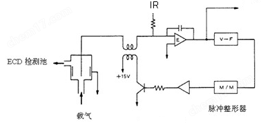
image1.11 ECDDevice schematic diagram
WarningImproper operation, radioactive source(63Ni)It will cause personal injury to you, and it is strictly prohibited not to take professional protective measures
DismantlingunloadECDDetector! During use, exhaust gas should be directed outdoors!
Warning: Radioactive source(63Ni)It is subject to strict material control, strictbanECDDiscard the detector as ordinary waste!
WarningEquipment scrap, radioactive source(63Ni)Should be returned to the manufacturer for processing or sent to a professional qualified manufacturer for recycling and disposal!
1.4.7 Flame photometric detectiondevice(FPD)
FPDIt is a highly selective and sensitive detector for phosphorus and sulfur compounds. When the sample is burned in a hydrogen rich flame, the phosphorus containing organic compound emits a wavelength of526nmoffeatureLight, sulfur-containing compounds emit with a wavelength of394nmThe characteristic light. The photomultiplier tube converts light signals into electrical signals, which are amplified by microcurrents and recorded.FPDBeneficial for the analysis of trace phosphorus and sulfur.
As shown in the following figure,FPDIt mainly consists of two parts: the flame part and the photoelectric conversion part.The flame section consists of a burner and a light chamber. The effluent from the gas chromatography column and excess hydrogen gas enter the combustion hole, forming a diffused hydrogen rich flame with air. Hydrocarbons, sulfur, and phosphorus compounds decompose in the flame and undergo complex chemical reactions, emitting characteristic light. Sulfur and phosphorus diffuse in the upper part of the flame and emit light in the hydrogen rich flame, while hydrocarbons mainly emit light in the oxygen rich flame at the bottom of the flame. Adding an opaque light shield at the bottom of the flame to block the interference of hydrocarbons improves efficiencyFPDThe selectivity. To reduce the volume of the light-emitting chamber, glass or quartz tubes are added above the nozzle to lower the response time constant of the detector.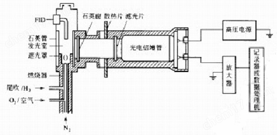
image1.12 FPDSystem Schematic Diagram
The right side is the photoelectric conversion part. In order to avoid the influence of a large amount of water vapor, combustion products, and high temperature generated in the flame on the photoelectric conversion system, quartz windows and heat sinks are used to separate the light-emitting chamber from the photoelectric system.FPDNot converting all light into electrical signals, but using filters to select characteristic light of sulfur and phosphorus.
WarningIt is strictly prohibited to turn on the high-voltage power supply when the detector is leaking light!
1.4.8 Display screen and keyboard
PS-8001gas chromatographThe display screenfor192*64Chinese character LCD display screen, keyboard design is simple and clear, fully functional, easy to operate, and easy to learn and use. In this capitalmaterial3.1There is a detailed introduction in the chapter.
1.4.9 External event control and communication output
PS-8001gas chromatographExternal events are controlled within the instrument. On the left side of the control motherboard, there is a column for air path control output (optional)matchEFCTheEPCThe column on the right represents the output of external event control; Two terminals are grouped from top to bottom. The gas path control outputs are: carrier gas (nitrogen), hydrogen, air, ignition control; The external events are:document1The matterdocument2The matterdocument3(or alarm output), eventdocument4(or rapid cooling control) output.
Communication acquisition of instrumentsuse10M/100MAdaptive Ethernet interface. The signal output can be an analog signal or communicate with an optional dedicated workstation through a local area network.
Note:matterdocument3When generating alarm outputs, it is necessary to第3The external event time program does not need to be reset (all reset).
matterdocument4When implementing rapid cooling control, it is necessary to第4The external event time program does not need to be reset (all reset).
The power switch is the main power switch of the instrument.
WarningWhen opening the instrument casing, if there is a possibility of touching the electrical parts, the power plug should be unplugged from the power source! Turn off the power switch,
Some circuits inside the instrument still have high voltage present!
1.5 Application environment of the instrument
1.5.1 Installation environment
****gas chromatographThe temperature and relative humidity should be5~35℃and0~85%Used within the scope. This way, the instrument can perform at its best and have the longest service life.
If the instrument is exposed to corrosive substances (whether they are gases, liquids, or solids))In the middle, it will endangerPS-8001gas chromatographMaterials and components should be avoided.
install****gas chromatographThe test bench must be stable. The vibration of the test bench can affect the stability of the instrument. In order to timely discharge the hot air from the column furnace, at least a space should be left behind the instrument30cmSpace should be reserved (and flammable materials should not be placed behind!), and a workbench should also be left30—40cmThe passage is designed for the installation and maintenance of instruments.
1.5.2 Power environment
gas chromatographConnect the power supplyfor220V±10%(50Hz±0.5 Hz)The power that can be provided is not smallYu2500WIn order to protect personal safety,gas chromatographAccording to the requirements of the International Electrotechnical Association, use a three core power cord for grounding.
noteTo reduce the electrical noise of the instrument, it is necessary to have a good grounding.
WarningIt is strictly prohibited to replace grounding wires with water pipes, gas pipes, neutral wires, etc!Please refer to the appendix for details!
1.5.3 Gas environment
to ensuregas chromatographThe optimal performance requires the gas used to reach the corresponding purity level. We recommend the following purity values.
detector |
Gas action |
gas name |
purity |
FID |
carrier gas |
HeorN2 |
not smallYu99.999% |
TCD |
carrier gas |
HeTheH2orN2 |
not less than99.999% |
ECD |
carrier gas |
N2 |
not less than99.999%(Need to removeoxygen) |
FPD |
carrier gas |
HeorN2 |
not less than99.999% |
|
Tail blowing |
HeorN2 |
not less than99.99% |
|
gas |
H2 |
not smallYu99.99% |
|
Assisting Gas |
Air |
As clean and dry as possible |
We suggest installing a purifier on the gas path! After using the gas purifier for a period of time, the molecular sieve and silica gel inside the purifier should be activated.
After the instrument arrives, please check the quality of the outer packaging of the instrument in a timely manner. If there is any damage, please contact the manufacturer or seller immediately. After unpacking, please count the supporting components. If you find that the supporting components do not match or the appearance of the instrument is damaged, please contact the manufacturer or seller immediately to avoid unnecessary economic losses or delays in your work.
2.2 Installation of instruments
After checking for accuracy, carefully place the instrument in a suitable position on the workbench. The workbench must be stable. Do not stack flammable materials behind the instrument and leave space for installation and maintenance.
2.2.1 Installation of gas source
usegas chromatographPlease refer to beforephoto1.5.3placenarrate, recount, state,And according to what you want to useThe type of detector is equipped with a gas source.
Please install the gas source in a safe location. If a steel cylinder gas source is used, the cylinder should be fixed to prevent tipping over and accidents. Regardless of the form of gas source chosen (such as steel cylinder gas source, hydrogen generator, air compressor, etc.), it is necessary to carefully check whether the quality of the generated gas meets the requirements of the gas chromatographRegarding QiRequirements of the source. To avoid affecting the analysis results or causingPollution and even damage to the chromatograph!
2.2.2 Installation of pressure reducing valve
If using a steel cylinder gas source, the installation steps for the pressure reducing valve are as follows:
1. Unscrew the low-pressure bamboo joint connector attached to the gas pressure reducing valve, connect the pressure reducing valve adapter, and screw on the low-pressure output adjustment rod (do not tighten it).
2. After installing the pressure reducing valve onto the steel cylinder and tightening the nut, open the main valve of the cylinder, and the high pressure gauge should indicate.
3. After closing the switch valve of the steel cylinder, the high pressure gauge of the pressure reducing valve should not decrease. Otherwise, if there is any leakage, it should be eliminated before use.
2.2.3 Installation of external air circuit
The gas pipeline of this gas chromatograph is mainly used for gas transmissionyesF3x0.5Polyethylene pipeorF3x0.5Stainless steel conduit (self provided). Cut the gas pipeline into three sections according to the required length, and connect the gas source to the chromatograph according to the gas type and the label at the back of the instrument.
Note:1Cut an appropriate length of polyethylene pipe and insert one at each endrootΦ2×0.5The stainless steel lining tube.
2, willM8×1Install the sealing nut and gas path sealing gasket into one end of the polyethylene pipe, screw it onto the steel cylinder adapter, and
Tighten to ensure good sealing.
3, willM8×1Install the sealing nut and gas path sealing gasket into the other end of the polyethylene pipe. Connect to the rear of the host
Should be connected(M8×1)Up and tighten to ensure good sealing.
4 Gas chromatography can also be used for samplinguseΦ3×0.5Stainless steel or copper tube with outer diameter is used as the external air path
The connecting pipe.
Attention:
1. When necessary, pipelines should be used to connect the gas flow diversion vent and detector vent to the outside to avoid analysishave Indoor air pollution caused by toxic and harmful substances;
2. In practical operation, pay attention to frequent leak detection! Once a leak occurs somewhere, it can affect the normal operation of the instrument or cause accidents (such as a hydrogen leak that may cause an explosion)!
3. The pressure of the carrier gas input into the chromatograph must be within343KPa—392KPaWithin the scope (equivalent to3.5kg/cm2—4kg/cm2);
4. The pressure of air input into the chromatograph must be within294KPa—392KPawithin the scope of(equivalent to3kg/cm2—4kg/cm2);
5. The pressure of hydrogen input into the chromatograph must be within196KPa—392KPawithin the scope of(equivalent to2kg/cm2—4kg/cm2);
6. If hydrogen is used as the carrier gas, the inlet pressure of the carrier gas input to the chromatograph should be343KPa(equivalent to3.5kg/cm2).
After the installation of the external air circuit is completed, leak detection should be carried out to avoid accidents. Leak detection can be performed according to the following steps:
(1)Close all carrier gas stabilizing valves, flow stabilizing valves, hydrogen and air stabilizing valves on the host;
(2)Place the low pressure regulating rod of the steel cylinder in a relaxed state, open the main valve of the steel cylinder, and slowly adjust the low pressure regulating rod to make the low pressure gauge indicatefor3kg/cm2;
(3)Close the high-pressure valve of the steel cylinder. At this time, the low pressure gauge on the pressure reducing valve should not decrease. Otherwise, if there is a leak in the external air path, it should be carefully checked and eliminated.
3 *****Operation of gas chromatograph host
3.1 keyboard operation
gas chromatographIndependent temperature control settings and temperature control can be performed for six temperature control zones. And the chromatographic column box is equipped withhave16Step program heating function. The rear door of the column box will automatically open or close according to the temperature control algorithm of the column box.
*****display screenfor192*64The Chinese character LCD screen allows for a clear view of the working status of the instrument. The keyboard design is concise, clear, fully functional, and easy to operate.

Schematic diagram of keyboard and indicator lights
*****gas chromatographThe operation keyboardtogether20An operation button toand3Status indicator lights:
start The key is the temperature control start key (pressed for the first time during startup) or the signal analysis and program temperature rise start key (after constant temperature state).
Attention: If the preparation light is not turned on, pressstartThe key lift is invalid.
end The key is the button to stop program heating when the signal analysis is completed or the program is heating up.
dormancy The key controls the display screen to turn off or on, without affecting the working condition of the instrument. It can extend the service life of LCD screens.
injection The key allows users to set relevant parameters when selecting a liquid automatic sampler.
Settings The key is used to enter the setting state of the instrument; After entering the setting state, the content to be set will be displayed in reverse.
△ The key is the flip up button on the display interface; In the setting state, the set position can be moved upwards.
▽ The key is the scroll down button on the display interface; In the setting state, the set position can be moved downwards.
input The key is used to confirm the parameter settings.
Intermediate composite bondtogether12One. Set the status as a number on the key、“deleteexcept”and“.”Function keys; When not in the set state, press the function keys shown in the lower part of the keys lightly to enter the corresponding interface display of the instrument.
prepare The continuous illumination of the light indicates that the measured temperature of each control unit that allows temperature control has reached the set value, with the column furnace temperature being the set valueof±1℃, others are temperature settingsof±6℃At this point, functions such as sample injection and process lift can be activated.
fault The long light indicates that the instrument has malfunctioned and will display the cause of the malfunction, reminding the user to troubleshoot in a timely manner.
online lampLong dark, short brightIndicates that the instrument is working but not connected to the optional control workstation;Long bright, short darkIndicates that the instrument is working and successfully connected to the control workstation;Long bright or long darkIndicates that there is an internal malfunction in the instrument that needs to be checked.
Note:After entering the settings state, there is no keyboard operation,5After minutes, it will automatically exit the setting state.
When the temperature control system malfunctions, it may cause temperature loss of control. When the measured temperature in any temperature control area reaches the set protection temperature, the microcomputer controller will automatically cut off the heating power supply and display an over temperature alarm in the status display area of the monitor.
3.1.1 Viewing and Setting Temperature Control
When the instrument is turned on, presstemperaturePress the key to enter the temperature display state of the instrument, and you can view the operating status of each temperature control channel, as shown in the following figure:
temperature |
Cheng Sheng |
event |
traffic |
document |
network |
||
control district |
enable |
setting |
actual measurement |
||||
Sample injector: |
open |
40℃ |
026.0℃ |
||||
pillar Furnace: |
open |
200℃ |
030.3℃ |
||||
Detector: |
close |
100℃ |
029.3℃ |
||||
inspect measure2: |
close |
134℃ |
606.7℃ |
||||
assist help1: |
close |
135℃ |
029.5℃ |
||||
assist help2: |
close |
136℃ |
606.8℃ |
||||
Temperature controlled statestate knot bundle | |||||||
control district |
guarantee protect |
form state |
|||||
Sample injector: |
060℃ |
open |
|||||
pillar Furnace: |
270℃ |
open |
|||||
Detector: |
120℃ |
close |
|||||
inspect measure2: |
154℃ |
close |
|||||
assist help1: |
155℃ |
close |
|||||
assist help2: |
156℃ |
close |
|||||
wait…000.00 10:00 | |||||||
Control areaIt's obviousshow6The name of the road temperature control, which has been configured at the factory; If modifications are needed, they can be made through the control workstation software (optional).
enableyesTranslate into English6Set the road temperature control to working or off state.“open”Indicate work status,“close”Indicates a closed state. When a certain temperature control is setfor“open”When in the state, the temperature control of this circuit is pressedmove start Afterwards, it will be in a heating and temperature control state, and its temperature control error will serve as the basis for preparing the light to turn on. When a certain temperature control is setfor“close”When in the state, the temperature control of this circuit is pressedmove start Afterwards, it is not in the heating and temperature control state, and the temperature value of this circuit isprepareThe light is not on.
SettingsIt's obviousshow6The set temperature for road temperature control.
actual measurementIt's obviousshow6The measured temperature of road temperature control.
protectIt's obviousshow6The protective temperature for road temperature control. The temperature is automatically calculated by the instrument based on the temperature set by the user and does not require modification.
statusIt's obviousshow6Is the road temperature control in a heating state. This status is automatically displayed by the instrument based on the temperature control status and does not require modification.
press Settings The key can cause a certain parameter to be displayed in reverse (this is the setting state, the same below!). If no setting is required, press it againSettings Press the key to exit the settings. In the setting state, press ▽ key 、 △ You can choose to set other parameters by pressing the key, enter numerical values by pressing the number key, and pressinput The key will save the set parameters to the instrument and automatically enter the next setting. In the non set state (no reverse display state on the interface), if you press ▽ key 、 △ The key can switch to other operation interfaces, and the parameter setting steps are as described above.
Note:When setting up various channelsof“makecan”When in a state, pressdeletekeyfor“makecan”On/off status switch key.
noteWhen the parameters change, if not pressedinput Key, setting parameters only as display content and not saved or executed by the instrument; the same below
3.1.2 Turn on or off the temperature control system operation
When the instrument is turned on, pressstartPress the key to put the instrument into temperature control mode. At this point, you will hear a relay closing sound inside the instrument,“makecan”for“open”Each temperature control area will be heated and temperature controlled. sametime“status”The bar will display the heating status of each channel. If it has not entered the temperature control state, thenthis“formstate”Display all columnsshow“close“.
When the temperature of the column box reaches the set valueof±1℃The temperature of all other enabled channels has reached the set valueof±6℃time,“accurateprepare”The light is illuminated, and the status display area below the keyboard will also appearnow“accurateprepare”word.
note:when“accurateprepare”When the light is on, if you press againstartThe key will start the control workstation (optional) and enter the analysis state; At the same time, if the program heating parameters and external event parameters are valid, the instrument will enter both the program heating state and the external event control state simultaneously.
In the temperature controlled state of the instrument, pressCloseThe key will display the following interface:
inspect1 |
inspect2 |
inspect3 |
stopwatch |
Close |
About |
|
Turn off temperature control? Attention: After turning off the temperature control Turn off the power according to the operating procedures and loadqi! | |||||
When in the interfaceof“Turn off temperature control?”Reverse display, such as pressinginputPress the key to turn off temperature control. At this point, you will hear a relay release sound inside the instrument, and the rear door will automatically open for cooling; If pressedSettingskey,“Turn off temperature control?”Stop reverse display, that is, exit the interface settings. At this time, press other keys to switch the interface.
3.1.3 Viewing and Setting Program Temperature Rise
When the instrument is turned on, pressCheng ShengPress the key to enter the program temperature display state of the instrument (it can also be in a non set state)press ▽ Key or △ Press the key to enter, as shown in the following figure:
temperature |
Cheng Sheng |
event |
traffic |
document |
network |
||
at initializationinterval005.0 min | |||||||
1step |
10.0℃/min |
250℃ |
010.0 min |
||||
2step |
00.0℃/min |
000℃ |
000.0 min |
||||
3step |
00.0℃/min |
000℃ |
000.0 min |
||||
4step |
00.0℃/min |
000℃ |
000.0 min |
||||
5step |
00.0℃/min |
000℃ |
000.0 min |
||||
6step |
00.0℃/min |
000℃ |
000.0 min |
||||
7step |
00.0℃/min |
000℃ |
000.0 min |
||||
8step |
00.0℃/min |
000℃ |
000.0 min |
||||
9step |
00.0℃/min |
000℃ |
000.0 min |
||||
10step |
00.0℃/min |
000℃ |
000.0 min |
||||
11step |
00.0℃/min |
000℃ |
000.0 min |
||||
12step |
00.0℃/min |
000℃ |
000.0 min |
||||
13step |
00.0℃/min |
000℃ |
000.0 min |
||||
14step |
00.0℃/min |
000℃ |
000.0 min |
||||
15step |
00.0℃/min |
000℃ |
000.0 min |
||||
16step |
00.0℃/min |
000℃ |
000.0 min |
||||
wait…000.00 10:02 | |||||||
Program heating refers to the process in which the temperature of the column box needs to change according to the set value during sample analysis.
Above the interface is the initialization time, which is the time required to wait for the start of heating up; middle第1Listed as the order of promotion;第2Listed as heating rate;第3Listed as termination temperature;第4Listed as holding time. At the bottom of the interface, the status display area will show the current running status of the instrument, the stopwatch will record the waiting time, and the current time.
Note:Parameter setting同3.1.1The temperature setting.
Note:The termination temperature of Cheng Sheng should be set higher than the set temperature of the column furnace, and the next stage temperature should be higher than the previous stage temperature.
Note:When the heating rate of a certain orderfor0This will render the program heating of this stage and subsequent stages ineffective;第1Step heating ratefor0It will render the entire program's heated content invalid.
Program heating operation:
When the instrument is turned on, pressstartPress the key to enter the temperature control state of the instrument, when the instrument is in operationYu“accurateprepare”After the status, press againstartThe key will initiate the temperature control program for the instrument. Timing stopwatch in the status display area(00.00)The timer will start. At the same time, it will also display which level Cheng Sheng has reached, such asshowNO.01Indicates that the execution is the first stage program heating up, and so on.
When the chromatograph executes the program to heat up and enters the initial temperature holding state, the display area showsshow“beginningWen”;
When the instrument enters the heating state, the display area showsshow“riseWen”When the instrument enters the temperature holding state, the display area showsshow“guaranteehold”When the instrument enters the cooling state, the display area showsshow“dropWen”.
After the instrument completes a complete program heating cycle, the stopwatch in the status display area will end timing; The instrument will automatically open the back door of the column box to quickly reduce the temperature inside the column box to the initial temperature, shortening the cooling time of the instrument. When the temperature inside the column box drops to the initial temperature(±1℃),“accurateprepare”The light is turned on again, waiting for the next program to start heating up. So repeatedly.
When the instrument is programmed to heat up, under the temperature control system,press“停止”The key will interrupt the program's heating status, and the timing stopwatch in the status display area will be displayed(00.00)The timer will end and reset, and the instrument will return to its initial temperature state.
3.1.4 Viewing and Setting External Events
When the instrument is turned on, presseventPress the key to enter the external event time program display state of the instrument. As shown in the figure below:
temperature |
Cheng Sheng |
event |
traffic |
document |
network |
|||
第1road time program(min) | ||||||||
00.00 |
00.00 |
00.00 |
00.00 |
|||||
00.00 |
00.00 |
00.00 |
00.00 |
|||||
第2road time program(min) | ||||||||
00.00 |
00.00 |
00.00 |
00.00 |
|||||
00.00 |
00.00 |
00.00 |
00.00 |
|||||
第3road time program(min) | ||||||||
00.00 |
00.00 |
00.00 |
00.00 |
|||||
00.00 |
00.00 |
00.00 |
00.00 |
|||||
第4road time program(min) | ||||||||
00.00 |
00.00 |
00.00 |
00.00 |
|||||
00.00 |
00.00 |
00.00 |
00.00 |
|||||
knot bundle | ||||||||
|
Attention: This time program Run until the output is closed at odd times, Run until even time output is disconnected. timefor0At the moment, the time program ends. | ||||||||
wait…000.00 10:02 | ||||||||
Note:Parameter setting同3.1.1The temperature setting.
noteWhen:第3Set the travel time program tocomplete00When,第3The output of external events is an alarm signal. when第3The road time program is equipped withnot0When setting parameters, it will同1、2Output of time program.
noteWhen:第4Set the travel time program tocomplete00When,第4The output of external events on the road is rapid cooling control. when第4The road time program is equipped withnot0When setting parameters, it will同1、2Output of time program.
3.1.5 Viewing and setting of detectors
When the instrument is turned on, pressinspectmeasure1、inspectmeasure2、inspectmeasure3You can view and set the installed detectors separately. When a detector is not installed at a certain position, the system will display:
|
Detector not installed Please check! |
For already installed了1~3When using a detector,pressinspectmeasure1、inspectmeasure2、inspectmeasure3The key instrument will automatically display the following interface:
whenFID1When installed, it displays:
|
FID1polarity0 range*10 20time/S Empty baseline deductnoneeffect pointfire? FID1信number: 0,000,000uV |
whenFID2When installed, it displays:
|
FID2polarity0 quantityCheng*10 20time/S Empty baseline deducthaveeffect pointfire? FID2signal:0,000,000uV |
whenFPDWhen installed, it displays:
|
FPDpolarity0 quantityCheng*10 20time/S Empty baseline deductnoneeffect FPD信number: 0,000,000uV |
The range of the above detectors can only be selected for inputenter“7”、“8”、“9”or“10”;Entering other numbers is invalid and will sound an alarm. the same below
whenECD1When installed, it displays:
|
ECD1range0 baseflow0.05nA20time/S Empty baseline deductnoneeffect ECD1signal:0,000,000uV |
whenECD2When installed, it displays:
|
ECD2range0 baseflow0.05nA20time/S Empty baseline deductnoneeffect ECD2信number: 0,000,000uV |
ECDThe range of the detector can only be selected for inputenter“0”or“1”.“0”Indicates to remain unchanged;“1”Indicating a doubling of the measurement range. Basic flow selectable inputenter“0.05”、“0.1”、“0.2”、“0.5”、“1”or“2”Six values, other values are invalid.
whenTCD1When installed, it displays:
|
TCD1polarity0 Bridge flow000mA20time/S Empty baseline Deduction is invalid TCD1信number: 0,000,000uV |
whenTCD2When installed, it displays:
|
TCD2polarity0 Bridge flow000mA20time/S Empty baseline deductnoneeffect TCD1信number: 0,000,000uV |
Selection of input value range for bridge current:0~200mAThe other values are invalid.
“Empty baseline”To: When the instrument is in preparation and the baseline has stabilized (baseline drift does not exceed the technical specifications), perform a programmed temperature rise before injection, and record the baseline drift data caused by the programmed temperature rise. Hover the cursor overEmpty baselinePress hereinputAfter pressing the key, the instrument will automatically start the program heating (the program heating parameters are valid) and begin recording baseline data; pressendStop empty baseline recording with the key. Maximum recording time of empty baselinefor2An hour and stored by the instrument. The stored empty baseline data will be stored in the next steptime“Empty baseline”The command is automatically updated at the beginning.
“Deduction haseffect”、“Deduction Noneeffect”Indicate whether the baseline stored by the instrument in the analytical state is involved in baseline deduction.
Note:Parameter setting同3.1.1The temperature setting.
Note:Polarity numbers can only be inputtedenter“0”or“1”, other numbers are invalid,“0”Indicates that the output data remains unchanged,“1”When the polarity of the output data changes, the corresponding spectrum will flip.
noteWhen selecting a control workstation, the sampling rate of the detector must be setfor20time/STo adapt to the data department
Manage software.
note:“Empty baseline”、“Deduction haseffect”、“Deduction Noneeffect”Only valid when selecting a control workstation. If deduction is set to be valid, the baseline data stored inside the instrument must be the correct baseline, otherwise the output of the instrument will be in an unknown state.
note:TCDThe use of detectors must comply withguard“First ventilate, then heat up, and then electrifyflow”The principle. alsowhenTCDDo not set the bridge current when the detector is not loaded with gas, otherwise it will damage the tungsten wire! When shutting down, be sure to first turn off the bridge flow and then cool downwaitTCDTurn off the carrier gas after the temperature drops to around room temperature!
note:TCDPlease try not to use excessive current during operation. High current operation will accelerate the oxidation of tungsten wire and damage the lifespan of the detector.
noteTo preventstopTCDThe damage to the detector is caused by the use of bridge current setting values in the design of this machine, which are not saved after shutdown. That is, the machine is turned ontimeTCDAutomatic bridge flow setting valuefor0Milliampere.
Warning:When the carrier gas contains oxygen, it willmakeTCDThe lifespan of tungsten wire is shortened. The carrier gas must be deoxygenated at the bottom!
3.1.6 gasProtection and controlfunctionandEPCTheEFCViewing modules
Gas protection refers to the use of pressure sensorsorEPCModule and other technical measures, when the input pressure of the carrier gas cannot reachto0.05MPaAt that time, the instrument automatically shuts down for temperature controlandTCDDetector bridge flow, etc., to prevent damage to the instrument.
This instrument can use mechanical valvesorEPCTheEFCModule (optional) controls the flow or pressure of the air circuit. For detailed operation of mechanical valves, please refer to:3.2 Gas flow control mechanical valve.
3.1.6.1 gasViewing pressure and flow rate
When the instrument is turned on, presstrafficPress the key to enter the gas parameter display state of the instrument. When the instrument is equipped with traditional mechanical valves to control gas flow and electronic pressure and flow sensors (optional) are used to measure pressure and flow, follow thetrafficThe key will display as follows:
N2:000.00 H2:000.00 AIR:000.00 |
|
INJ1-EFC: chromatographic column:000.0sccm 000.00sccm |
divide flow:000.0sccm 000.00sccm |
|
blow sweep:000.0sccm 000.00sccm split ratio:1/1 1/1 Cheng Sheng Settings: At the beginninginterval000.0min ----quickrate-----------guaranteehold----------timeinterval------- 000sccm/min 000sccm 000.0min 000sccm/min 000sccm 000.0min 000sccm/min 000sccm 000.0min 000sccm/min 000sccm 000.0min |
|
Mode settingplace: stableflow Gas equipmentplace0 chromatographic column:D=0.32mm L=015.000m divide flow:D=0.10mm L=000.040m blow sweep:D=0.10mm L=000.040m |
Gas type: Nitrogen:0hydrogen:1empty:2helium:3 |
The first line showsshowN2TheH2TheAIRThe pressure after the pressure reducing valve.
The middle part displays the sample injectiondevice1(INJ1)The set parameters for flow rate, measured flow rate, set split ratio, measured split ratio, and chromatographic column lift pressure (or flow rate).
The lower part is for injectiondevice1(INJ1)The working mode, gas type, and specifications of the chromatographic column, as well as the gas resistance parameters used for diversion and purging.
At this moment, press▽ key 、 △ The key can view the injection sampledevice2(INJ2)Sample injectiondevice3(INJ3)Testingdevice1(DET1)Testingdevice2(DET2)Wait, waitofEFCModule parameters.
detectiondeviceEFCDisplay and setting interface:
N2:000.00 H2:000.00 AIR:000.00 |
|
DET1-EFC: hydrogen qi:000.0sccm 000.00sccm |
empty qi:000.0sccm 000.00sccm |
|
tail blow:000.0sccm 000.00sccm Tail blowingbody: 0 hydrogen qi:D=0.10mm L=000.040m empty qi:D=0.25mm L=000.040m tail blow:D=0.10mm L=000.040m |
|
DET2-EFC: hydrogen qi:000.0sccm 000.00sccm empty qi:000.0sccm 000.00sccm tail blow:000.0sccm 000.00sccm Tail blowingbody: 0 hydrogen qi:D=0.10mm L=000.040m empty qi:D=0.25mm L=000.040m tail blow:D=0.10mm L=000.040m |
Note:Only instrument optional installationhave“Electronic pressure and flow measurement moduleblock”、“EPCandEFCControl moduleblock”When,
This parameter is meaningful.
Note:Gas type, chromatographic column, bypass gas barrier, purge gas barrieryesEFCThe control module is an extremely important parameter, only
Only when the configuration is correct can the module work properly.Split flow air resistance and blow off air resistance are matched according to actual production when the instrument leaves the factory
Set, user cannot modifyIf the data is lost or incorrect, please consult the manufacturer.
Note:whenEFCWhen the module is used to fill the display of the column injector, the chromatographic column parameters are meaningless.
The function of the electronic pressure and flow measurement module is to replace traditional pointer pressure gauges with pressure and flow sensors to measure the pressure and flow of the working gas. It has the advantages of high measurement accuracy and intuitive display.
When the instrument is selectedWhen the electronic pressure and flow measurement module is in operation,presstrafficPress the key again▽ The key can view gas protectionGas configuration and dynamic configuration parameters of electronic pressure and flow measurement modulesThe interface is as follows:
|
Gas protectionprotectN2:openH2:open AIR:close Gas setting: nitrogen0 hydrogen:1 empty:2 helium:3 01->0 02->1 03->2 04->3 05->0 06->1 07->2 08->3 09->0 101 11->2 12->3 13->0 14->1 15->2 16->3 |
|
dynamic configuration: No need to close it:88 01->0002->0103->0204->10 05->10 06->12 07->13 08->14 09->15 1016 11->17 12->18 13->88 14->88 15->88 16->88 total press: nitrogenqi00 hydrogenqi01 emptyqi02 injectiondevice1: loadqi10 divideflow11 blowsweep12 injectiondevice2: loadqi13 divideflow14 blowsweep15 detectiondevice1: hydrogenqi20 emptyqi21 tailblow22 detectiondevice2: hydrogenqi23 emptyqi 24 tailblow2 Please check the instrument configurationplace,Careful repairchange! |
Gas protection refers to the use of pressure sensorsorEPCModule and other technical measures, when the input pressure of a certain gas cannot reachto0.05MPaThe instrument automatically shuts down for temperature controlTheTCDThe function of the detector bridge flow. When settingfor“open”At that time, the pressure of this gas wasto0.05MPaWhen the instrument automatically shuts down; When settingfor“close”At this time, the gas pressure on this path will not participate in gas protection.
When the instrument is not equippedprepare“Gas protectionprotect”When using hardware (such as not equipped with pressure sensors)orEPCModule), the setting no longer has any meaning, the instrument can be turned on normally, but there is no corresponding protection function.
Note:Only instrument installationhave“Electronic pressure and flow measurement moduleblock”、“EPCandEFCControl moduleblock”At that time, Ben
The parameters are meaningful.
WarningUnless there is an error, please do not change the parameters of the instrument configuration at will!
When the instrument is selectedWhen the electronic pressure and flow measurement module is in operation,presstrafficKey, thenpress2time ▽ Key can be viewedCapillary parameters or gas resistance parameters of electronic pressure and flow measurement modulesThe interface is as follows:
|
Fine column and air resistance configuration: qiblock01:D=0.10mm L=000.115m qiblock02:D=0.10mm L=000.115m qiblock03:D=0.10mm L=000.115m qiblock04:D=0.10mm L=000.115m qiblock05:D=0.10mm L=000.115m qiblock06:D=0.10mm L=000.115m qiblock07:D=0.10mm L=000.115m qiblock08:D=0.10mm L=000.115m qiblock09:D=0.10mm L=000.115m qiblock10:D=0.10mm L=000.115m qiblock11:D=0.10mm L=000.115m qiblock12:D=0.10mm L=000.115m qiblock13:D=0.10mm L=000.115m qiblock14:D=0.10mm L=000.115m qiblock15:D=0.10mm L=000.115m qiblock16:D=0.10mm L=000.115m |
Gas resistance parametersof“D”forInner pore diameter of capillary column or gas barrier;“L”forThe length of a capillary column or gas barrier. Due to the calculated gas flow rateand“D”of4The power is proportional,and“L”Inversely proportional. So the correctness of setting this parameter directly affects whether the calculation result is correct.
The randomly equipped air resistance has undergone strict calibration and correction, and this value cannot be arbitrarily modified!
After installing or replacing the capillary column, the nameplate of the column (or consult the capillary column manufacturer) should be checked to correctly input the inner diameter and column length. To avoid discrepancies between the flow rate calculated by the instrument and the actual flow rate.
“Wool fine column and air resistance matchingplace”The setting method同3.1.1The temperature setting.
Note:The air resistance parameter for this item isElectronic pressure and flow measurement moduleThe parameters,andEFCThe control module is independent.!
Note:Only instrument installationhave“Electronic pressure and flow measurement moduleblock”Only then does this parameter have meaning.
3.1.7 Viewing and setting of execution files, automatic injection time, screensaver, clock, and language
When the instrument is turned on, pressdocumentPress the key to enter the display state of the time parameter for the instrument. As shown in the following interface:
temperature |
Cheng Sheng |
event |
traffic |
document |
network |
Current execution file:1Number file | |||||
|
Program settings for gas automatic sampler auto-sampling0006 time intervalpartition 008.0 minute (Number of injections)for9999When, for long-term injection) | |||||
|
Screen saver time:05 dividebell (99When it is always on FIDTheFPDDetector ignition time:0 second Clock Settings:10/06/21 14:09:20 Language Selection:0 0: Middletext 1:English | |||||
|
Machine Number:60F9-990A-4A48-485D Motherboard version:GCM-SUN-V2-1005 Display version:GCD-SUN-V3-1005 EPCversion:GCF-SUN-V1-1006 DET1version:GCT-SUN-V1-0911 DET2version:GCT-SUN-V1-0911 DET3version:GCF-SUN-V1-0911 | |||||
wait…00.00 10:02 | |||||
Note:Parameter setting同3.1.1The temperature setting.
Protect within this instrumentsave8An instrument operating parameter file. You can chooseuse0—7The number file serves as the file executed by the current instrument. After replacing the executable file, the instrument will be reinitialized. This will take a few seconds.
“entersample:0006time”Indicates that the system has automatically completedbecome6Secondary injection; whenfor0At this time, the automatic injection program will not be started. This function is only valid when equipped with a liquid automatic sampler. If not selected, the number of injections must befor9999Next time.
“intervalpartition:008.0divide” Indicates the time interval during which the system performs automatic sampling. It includes automatic repeated program heating (when the program heating parameters are valid), external event time program (when the time program parameters are valid), and remote start control workstation software to start analysis. whenfor0If the time is divided, the automatic sampling program will not be started;
“screenguarantee”To automatically turn off the display screen at the set time without pressing any keyboard, without affecting the instrument status.
FID,FPDThe ignition time setting of the detector can also be directly operated through the keyboard.
“timebell”The real-time clocks inside the instrument are as follows:year/moon/day time:divide:In seconds. The clock can also be modified remotely through the optional control workstation software.
Note:Screen saver time settingfor99The display screen does not turn off in minutes.
Note:When turned on, the screensaver time defaults tofor5minute; When any keyboard is pressed, the actual screensaver time will be the set screensaver time.
Note:Closing the display screen willmakeFIDbaselinehave10-20uVTo avoid affecting the analysis, please adjust the closing time to an appropriate value or set itfor99minute.
note:in“ready statedown”And the number of injections and the interval between injections are not the samefor0When, pressstartKey or in selection
After starting the analysis on the control workstation software, the instrument will enterenter“During automatic samplinginterval”Execution status, in
The status bar willhave“INJ0001”Flashing display. “INJ0001”Indicates that the instrument has entered automatic sampling mode
Status, and currently第0001Sample analysis.
Note:The machine number below is an electronic tag automatically generated by the chromatograph and cannot be modified. The version information is for this instrument
The software version information of each component is only displayed and cannot be modified.
3.1.8 Viewing and Setting Network Parameters
When the instrument is turned on, pressnetworkPress the key to enter the display state of network parameters for the instrument. As shown in the following interface:
temperature |
Cheng Sheng |
event |
traffic |
document |
network |
|
|
Chromatograph network parameters this machineIP:192.168.018.202 subnet mask:255.255.255.000 net close:192.168.018.001 | ||||||
|
Workstation network parameters Local locationreasonIP:192.168.018.003 Business OwnerpipeIP:192.168.018.199 Superior MasterpipeIP:192.168.018.198 | ||||||
Connection status | ||||||
|
Local processing: Business Supervisor: Superior supervisor: <——> | ||||||
wait…00.00 10:02 |
||||||
Note:This parameter is only valid when selected with a dedicated control workstation. Please refer to the instructions of the corresponding workstation.
3.1.9 Operation of a stopwatch
GC7820gas chromatographDesigned with a timing stopwatch(00.00). This stopwatch is used when the instrument is executing a temperature or time program. When the stopwatch is not in use by the system, users can use it for timing (such as measuring peak time, gas flow rate, etc.). pressstopwatchPress the key to start the stopwatch timer, then press againstopwatchThe key will end the stopwatch timer.
The following figure shows the stopwatch interface:
inspect1 |
inspect2 |
inspect3 |
stopwatch |
injection |
About |
|
Stopwatch function Set soap bubble flow meter reading:50ml Actual measured gas flow rate:000.0 ml/min | |||||
|
EPC&EFCzero adjustment Disconnect all gas sources Turn on the electricitysource15Minutes, after reaching thermal equilibrium Zero adjustment? | |||||
Note:Parameter setting同3.1.1The temperature setting.
Except for function keys.
Warning:When noneneedEPC&EFCWhen adjusting to zero, do not hold online“tunezero”Confirm! Otherwise, it will cause unpredictable consequences
Measurement results!
3.1.10 Viewing and Setting of Automatic Sample Injector
“injectiondevice”It refers to the automatic liquid sampler (such as:AOC-20iEtc.).
pressinjectionKey, will enterto“injectiondevice”The interface for viewing and setting. As shown in the figure below:
inspect1 |
inspect2 |
inspect3 |
stopwatch |
injection |
About |
|
Program settings for liquid automatic sampler timePreface bottlenumber entersample time/bottle interval 1: 002-003 01.0uL 003 010divide 2: 000-000 08.0uL 000 000divide 3: 000-000 08.0uL 000 000divide 4: 000-000 08.0uL 000 000divide
| |||||
|
Parameter settings for liquid automatic sampler auto-samplingdevice:have typenumber0 injection口0 Clear solvent before injectionwash:000time Sample cleaning before injectionwash:000time Clear solvent after injectionwash:000time Pump sample timesnumber:000time Viscosity delaytime:00.0second Sample injection stationstay:00.0second Sampling partyformula0 Injection needle speeddegree0 Needle core speeddegree0 Start delaytime:00.0hour formstate: Offline Emptyleisure whenfront:003-001 | |||||
The upper part of the interface is used to set up the batch processing program for the automatic sampler, such as from第2Number to第3Sample bottle number, injection volume per timefor1Microliters, repeat for each sample bottledo3Secondary analysis, time interval between each analysisfor10minute.
The middle part of the interface is used to set the basic parameters of the automatic sampler.
The lower part of the interface shows the current status of the automatic sampler,as“inline”、“leaveline”、“emptyleisure”、“entersample”Wait. The current bottle number refers to the number of sample bottles that the automatic sampler has executed and the number of injections in that sample bottle at the time of actual injection.
Note:When there is no automatic liquid sampler equipped, this parameter is meaningless.
Note:The basic parameters of an automatic sampler are determined by the model of the sampler equipped. Automatic entry for different models
The parameters set by the sampler are also slightly different. Please carefully read the instructions for using the automatic sampler provided!
Warning:Automatic sampler is a precision instrument. When installing and using an automatic sampler, please strictly follow its instructions,
To avoid damage!
3.1.11 FIDThe ignition operation
This instrument is designed with an automatic ignition function upon startup.
The conditions for automatic ignition upon startup are:
☆installhaveFIDDetector.
☆The instrument has adjusted the flow rate of hydrogen, and the air flow rate is based on the actual flow rateof2/3Adjust.
☆FIDThe actual temperature of the detector reachesto130℃Above, the ignition will be automatically executed.
☆After the instrument automatically ignites, adjust the air flow rate to the desired value.
When the ignition conditions are met, it can also be manually ignited at any time.
FIDManual ignition can be performed on the detector interface or directly by pressing the keyboardignitionKey executionline(The non set state is the ignition function key, and the set state is the decimal point inputkey)It can also be directly operated and executed in the control workstation software. Its ignition timefrom“When the detector igniteslong3second”The set time is automatically controlled, and users do not need to intervene.
Note:The electronic ignition component is an optional accessory. If the instrument is not equipped with an electronic igniter, it can be ignited with a gun or other ignition device.
Note:According to the actual application situation, the ignition time is generally set to3~5second.
Warning:The instrument is designed to be powered on (installed)haveFIDThe automatic ignition function after the detector is activatedPrevent electric shock,
Do not disassemble or assemble high-voltage discharge wires while the device is turned on!
3.2Operation of gas flow control
This instrument can use mechanical valves orEPCTheEFCThe module controls the flow or pressure of the gas path.
3.2.1Operation of flow control by mechanical valve
The carrier gas path is first stabilized by a pressure regulator valve, and the pressure is stabilized at3.5kg/cm2Left and right (already adjusted at the factory, users cannot adjust on their own!), then output a constant flow of carrier gas through a stabilizing valve.
adjust“carrier gasⅠ”or“carrier gasⅡ”The flow control valve can adjust the carrier gasⅠorⅡThe traffic.
tunesection“pre-columnpress”The regulating valve and pressure gauge indicate the corresponding pre column carrier gas pressure.
The air path is stabilized by a pressure regulator valve and combined with a fixed air resistance to output a certain flow of air. on the tablepress0.1MpaHourly traffic approximatelyfor400ml/minPlease refer to the air pressure provided with the instrument力—Flow curve chart.

Air pressure力—Flow Curve Diagram
The hydrogen gas path is stabilized by a pressure regulator valve,Combined with fixed air resistanceOutput a certain flow rate of hydrogen gas. In terms of gauge pressure0.1MpaHourly traffic approximatelyfor40ml/minPlease refer to the hydrogen pressure provided with the instrument力—Flow curve chart.
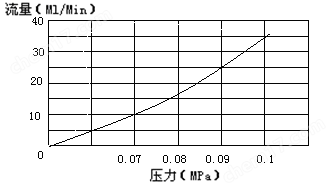
Hydrogen pressure力—Flow Curve Diagram
Note:When equipped with optional electronic pressure and flow measurement modules, pressure and flow values can be directly read from the instrument without the need for additional readings
Check the above curve.
3.2.2 EPC&EFCOperation of module controlled flow
This instrument can be optionally selectedEPCTheEFCThe module controls the flow or pressure of the gas path.
EPCTheEFCAll module operations are set using a keyboard or control workstation numerical settings. Please refer to the corresponding instructions.
4 Maintenance and upkeep of instruments
Injectors are prone to contamination, especially the inner liner. Therefore, it is important to clean the injector. The inner liner of the injector can be washed directly with solvent cotton balls, and after washing, blown with atmospheric flow (mainly to blow off the cotton ball fibers and dry the solvent), and then the inner liner tube can be installed“O”O-ring and sealing cap; When the pollution is severe, it is necessary to soak it in the corresponding solvent (or even washing solution) overnight, then clean it with ultrasonic waves, and finally rinse it with solvent, dry it, and store it in a dryer for later use.
4.2 Cleaning of hydrogen flame ionization detector
DetachableFIDCover, remove the electrode and insulating ceramic pad, clean the cover, electrode, and insulating ceramic pad with acetone or alcohol, and then dry them. If the pollution is severe, the parts to be cleaned can be placed in ultrasonic cleaning solution, cleaned with water after ultrasonic treatment, then washed with alcohol and dried. During assembly, pay attention to placing the polarizing coil around the nozzle and not touching the shell. The height should not exceed the nozzle opening. If it exceeds the nozzle opening, the polarizing coil will turn red after ignition, which will affect the stability and sensitivity of the detector. If the detector is contaminated by the chromatographic column fixative, a solvent that can dissolve the fixative should be selected for dissolution.
4.3 Installation of chromatographic column
4.3.1 Installation of filling columns
The installation of packed columns at both ends of the injector and detector is similar. If the column head injection method is used, there should be enough space left at one end of the injector for filling the columnpillar(tofew50mm)To prevent the inserted syringe needle from touching the glass fiber or column filling material filled at the end of the column; At one end of the detector, there should also be enough space leftpillar(tofew4mm)To prevent the bottom of the nozzle from touching the glass fiber or column filling material filled at the column end. As shown in the following figure:
Schematic diagram of the empty tubes at both ends of the column for filling the column with column head injection
*****gas chromatographΦ3mm(orΦ4mm)The connection between the packed chromatographic column and the injector/detector.
The installation steps are as follows:
1) Translate into EnglishM10×1 Φ3.2mm(orΦ4.2mm)Insert the column nut into both ends of the chromatographic column first.
2) Install at both ends of the chromatographic columnupΦ3mm(orΦ4mm)Insert the graphite ring upwards into the bottom of the injector and detector (to the bottom), and tighten the nut.
3) Use neutral soap solution for leak detection, there should be no air leakage.
4) Wipe off the soap solution.
Note:The injector end of the packed column should not be confused with the detector end and should be labeled when loading the chromatographic column, usually with
The aluminum label end is connected to the sample inlet end.
4.3.2 Installation of capillary column
The finished fused silica capillary column is very regular. After the column end passes through the sealing graphite gasket, it should be re cut. The cut should be free of burrs and the edge should be neat. Clean the part of the instrument to be connected with filter paper dipped in acetone to avoid introducing impurities that may interfere with the analysis. If there are still impurities interfering with a capillary column that has been used for a period of time after re aging, the injection port end should be cut offexcept30cmUse it left and right later.
Usually, the column nut and sealing graphite gasket are installed first before cutting. Use a suitable glass cutting tool (such as a wallpaper blade, etc.) to quickly cut through the desired area and gently tap off the end of the column.
Note:It is better to wear protective glasses to prevent possible eye injury caused by flying particles generated during processing and cutting fused silica capillary column. Caution should also be taken when handling capillary columns to prevent skin from getting pricked. Due to the toughness of the column, it is important to pay attention to these in advance when handling capillary columns.

Preparation of fused silica capillary column
The capillary column is wrapped around a metal frame, which is suspended on the capillary column bracket inside the column box. The two ends of the column extend from the bottom of the frame, smoothly bend towards the injector interface and detector interface, and do not let any part of the column touch the inner wall of the column box. When the graphite gasket passes through the column, it may contaminate the columnpress“Prepare fused silica capillarypillar”Cut the column end according to the instructions. The following figure shows the injection port end when installing an elastic quartz capillary columnandFIDThe length that needs to be reserved at the end.

4.4 gasfilterMaintenance of equipment
carrier gasIn the flow control system, such as the purge flow path of the filling column injection port, the diversion and purge flow path of the capillary injection port, all are connected to filters filled with adsorbents. Regular replacement or activation is required. When activating, the filter needs to be reversed and connected to the injection port in the direction of the carrier gas flow, and high-purity nitrogen should be introducedqi20ml/minThe activation temperature is260℃At that timeinterval10hour
5 Malfunctions and troubleshooting of instruments
5.1 No response upon startup
fault diagnosis |
Inspection methods and repairs |
Electricity supply issues |
Check the mains power supply |
Fuse blown |
Check the fuse and replace it |
The display screen does not light up |
Check the display screen leads |
5.2 Chromatographic peak issue
5. 2. 1No baseline
fault diagnosis |
Inspection methods and repairs |
The detection board is not installed |
Check if the detector board is installed |
Detection board malfunction |
Replace the detection board |
The chromatograph is not connected to the workstation |
Check the workstation and signal line connections |
fault diagnosis |
Inspection methods and repairs |
Injector temperature too low |
Increase the temperature of the sampler |
Syringe blockage |
Replace the syringe |
Amplifier power disconnected |
Check the amplifier |
No carrier gas passed through |
Check if the air flow path is blocked and if the gas in the cylinder has been used up |
Sample injection pad leakage |
Replace the injection pad |
Flame extinguished |
ignition |
FIDPoor polarization voltage contact |
Eliminate the phenomenon of poor polarization voltage connection |
5.2.3 normalretainSensitivity decreases over time
fault diagnosis |
Inspection methods and repairs |
Injector leakage |
Replace the syringe |
Improper selection of sensitivity |
Choose appropriate sensitivity |
There is a leakage point behind the carrier gas column |
Leak detection and corresponding treatment |
Improper selection of hydrogen and air flow rates(FID) |
Adjust their traffic flow |
The detector has no high voltage(FID) |
Check for polarization voltage |


