- Phone
-
Address
No. 100 Hengfeng North Road, Shanghai
Product Categories
Shanghai Suhai Electric Co., Ltd


SHXZ-180kVA/60kV Variable Frequency Series Resonant Voltage Endurance Test Device
NegotiableUpdate on 05/25
- Model
- Nature of the Manufacturer
- Producers
- Product Category
- Place of Origin
Overview
The 180kVA/60kV variable frequency series resonant withstand voltage test device uses the inductance of a reactor and the capacitance of the test object to form an LC series circuit, adjust the voltage frequency output of the variable frequency power supply, achieve series parallel resonance, and obtain high voltage on the test object. It is a new method of high voltage testing, highly praised by experts, and has been widely used at home and abroad.
Product Details
Details introduction:

SHXZ-180kVA/60kV Variable Frequency Series Resonant Voltage Endurance Test DeviceTechnical Solution
1. Basic principle of series parallel resonance:
1.1 Resonant voltage withstand test is a new method of high-voltage testing that uses the inductance of a reactor and the capacitance of the test object to form an LC series circuit, adjusts the voltage frequency output of the variable frequency power supply, achieves series parallel resonance, and obtains high voltage on the test object. It has been widely used both domestically and internationally and has received high praise from experts.
2. Characteristics of series parallel resonance test device:
2.1 The series parallel resonance test device has a large output capacity, high output voltage, and can freely combine reactors for AC withstand voltage testing of different test samples.
The series parallel resonance test device has small size, light weight, and is particularly convenient for field testing.
The series parallel resonance test device has good protection functions, including overvoltage protection, overcurrent protection, time protection, flashover protection, overheating protection, module protection, etc.
The 2.4 series parallel resonance test device is easy to operate and has two modes: manual and automatic.
The 2.5 series parallel resonance test device adopts a large screen, which makes the test data clear at a glance and can print the test results.
The series parallel resonance test device has no risk of overvoltage after the test sample is broken down, and the damage to the test sample is relatively small.
The power supply capacity required for the 2.7 series parallel resonance test device is small, only a fraction of the power supply capacity required for the power frequency transformer test, solving the problem of difficulty in finding on-site power supply.
3. Scope of Equipment Application
3.1Meet the AC withstand voltage test of 300mm2/10KV cable with a length of 3 kilometers.
4. Equipment manufacturing reference and execution standards
DL/T849.6-2004 "High Voltage Resonance Test Device"
GB 6450-1986 Dry type Power Transformers
DL/T848.2-2004 "Test Transformers"
GB/10229-1988 "Reactors"
GB/T11920-1989 General Technical Conditions for Control Devices
GB/T16927.1-1997 "High Voltage Test Techniques"
IEC358-1990 "Coupling capacitors and capacitive voltage dividers"
GB311.1 Insulation Coordination for High Voltage Transmission and Transformation Equipment
DL/T846-2004 General Technical Conditions for High Voltage Testing Equipment
Q/CSG10007-2004 "Preventive Testing Regulations for Power Equipment"
GB7328-87 "Sound Level Measurement of Transformers and Reactors"
DL474。 4-1992 "AC Voltage Endurance Test"
5. Environmental conditions for use
5.1 Surrounding air temperature:
*High temperature:+45 ℃ * Low temperature: -10 ℃;
*Large daily temperature difference: 35k Sunshine intensity: 0.1w/cm2
5.2 Altitude: ≤ 2000m;
5.3 Relative humidity: ≤ 90%
5.4 The installation and placement location should be flat, and the inclination of the reactor installation should not be less than 50 degrees;
There should be no gas vapor, chemical deposition dust, dirt, or other explosive media that seriously affect the insulation of the equipment around 5.5.
6. Specific equipment configuration
6.1 Test requirements:
6.1.1 AC withstand voltage test for 300mm2/10kv cable length of 3 kilometers. The test time is 5 minutes, the test voltage is 22kv, the test frequency is 30-300Hz, and the equivalent capacitance is 0.418uF/km.
6.2 Design of Reactor:
6.2.1. AC withstand voltage test for a 300mm2/10kv cable length of 3 kilometers The test time is 5 minutes, the test voltage is 22kv, the test frequency is 30-300Hz, and the equivalent capacitance is 1.254uF. When the frequency is 35Hz.
Test current I=ω CXU test=2 × 3.14 × 35 × 1.254 × 22 × 10-3=6A
Corresponding inductance of reactor L=1/ω 2C=16.5H
6.3 Configuration of Reactor:
6.3.1.300mm2/10kv AC withstand voltage test for a cable length of 3 kilometers, with a high test voltage of 22kV. For ease of handling, the reactor is divided into three sections, each with a voltage of 30KV, a current of 2A, and an inductance of 50H.
verification:
1) AC withstand voltage test for a 300mm2/10kv cable length of 3 kilometers The test time is 5 minutes, the test voltage is 22kv, the test frequency is 30-300Hz, and the equivalent capacitance is 1.254uF. Three reactors are used in parallel with a rated inductance of 16.6H, a rated voltage of 30kv, and a rated current of 6A.
Test frequency: f=1/2 π√ LC=34.8Hz
Test current I=ω CXU test=2 × 3.14 × 34.8 × 1.254 × 22 × 10-3=6A
6.4 Configuration of Excitation Transformer
6.4.1. As the quality factor Q value is not less than 20 at rated load, the excitation transformer has a total reactor capacity of 180KVA, which is divided by the quality factor of 20 to obtain 10KVA.
6.4.2. The specifications of the excitation transformer configured are YHXZB-10KVA/1.5kv/3kv.
6.5 Configuration of FM power supply:
6.5.1. The capacity of the frequency modulation power supply is equal to or greater than the capacity of the excitation transformer, which is taken as 10kvA.
6.5.2. The specification of the configured frequency modulation power supply is YHXZB-10kvA.
6.6 Configuration of capacitive voltage divider
6.6.1. Due to the high test voltage of 22kV, the voltage of the capacitive voltage divider is 30kV and the capacitance is 10000PF.
6.6.2. Configure one capacitor voltage divider with a specification of FRC-30kv/0.01uF.
7Equipment Test Wiring Diagram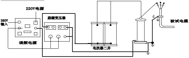


Similar Product Recommend
