-
E-mail
kh@zhkh.com
-
Phone
13825655906
-
Address
No. 8 Jinrui 1st Road, Jinding National High tech Zone, Zhuhai City, Guangdong Province
Product Categories
Zhuhai Kehui Electric Appliance Co., Ltd

PEC Transformer Calibration Device (10KV Transformer On site Testing Equipment)
NegotiableUpdate on 03/31
- Model
- Nature of the Manufacturer
- Producers
- Product Category
- Place of Origin
Overview
PEC Transformer Calibration Device (10KV Transformer On site Testing Equipment)
Product Details
This product consists of the following devices:
1、 One transformer calibrator

Features:
1The transformer calibrator has testing functions for voltage transformers, current transformers, impedance, and admittance, which facilitates on-site transformer calibration work.
2Internally equipped with high-power lithium batteries as the instrument's working power supply, the pure power supply brings more stable and accurate measurement data, while facilitating on-site calibration work.
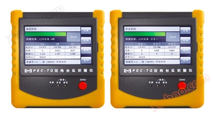
3Adopting a 640 × 480 high-resolution large screen LCD display, it has a user-friendly interface and operation design, and uses a touch screen to assist in operation, making the operation more convenient and fast.
4By adopting precise software algorithms, the accuracy of measurement data is further improved.
5It has intelligent judgment of external wiring status, prompting wiring errors, transformation ratios, polarity errors, etc.
6Automatically round the test data and determine if it exceeds the tolerance.
7Directly issue on-site inspection conclusions, whether they are qualified or unqualified.
8In the calibration of voltage transformers, the instrument has an internal voltage load box and does not require an additional voltage load box.
9The large-scale storage can store up to 1000 pieces of on-site test data.
10Adopting engineering plastic mold chassis for shock and pressure resistance, ensuring the safety of on-site operators and equipment.
Technical Specifications:
1.Measurement range:
f:0.0000%~200.0%(CT/PT)
δ:0.000′~999.9′
Z:0.0000Ω~100.0Ω
Y: 0.0000mS~100.0 mS
2.Accuracy of the whole machine: Level 1
3.Accuracy of working voltage, working current, and dial gauge: Level 0.5
4.Working voltage range:
5V~120V (100V: 1%~200%)
5.Operating current range:
50mA~10A (5A: 1%~200%)
6.Δ V measurement range: 0.1mV~200V (PT or impedance)
7.Δ I measurement range: 5uA~6A
8.Frequency error range:
40 Hz~60 Hz resolution: 0.1 Hz
9.Polarity indication:
Current: When the rated working current is above 1%, if there is polarity or transformation ratio error, there will be an alarm
Voltage: When the rated working current is above 2%, if there is polarity or transformation ratio error, there will be an alarm
10.Insulation test and instructions: The power socket can withstand 2KV and withstand voltage for 1 minute against the shell
11.The display screen of the transformer calibrator can clearly show the interface under strong sunlight, ensuring on-site use and reading
12.The ratio and angle difference of the transformer calibrator are directly read and have intelligent self checking function
13.The transformer calibrator has storage and upload/output functions that are consistent with the user's calibration certificate format, as well as corresponding interfaces. Its memory can meet the requirements of on-site work records and technical data after calibration processing
2、 1 standard current transformer0.02Slevel

Features:
This standard current transformer consists of a primary winding and a secondary winding.
Inspect according to the standard current ratio indicated on the nameplate.
It can perform self calibration with a current ratio of 5/5 or 1/1.
Equipped with casters for easy handling.
Technical Indicators:
Input: 0~250V
Temperature: -5 to+40℃
Humidity:<80%
Capacity: 5VA, COS diameter=0.8-1
Measurement range: 1% -140% In
Accuracy level: 0.02S level
Input voltage: 0V~250V
Current (A): 5, 7.5, 10, 15, 20, 25, 30, 40, 50, 60, 75, 80, 100, 120, 150, 200, 250, 300, 400, 500, 600, 750, 800, 1000, 1200, 1250, 1500, 1600, 2000
Secondary current (A): 5
test:
When calibrating a current transformer with an accuracy level two or lower than that of the current transformer, its circuit diagram is shown in Figure 2. In the figure, To represents the standard current transformer, Tx represents the tested current transformer, and Z represents the load carried by the tested current transformer. The output winding and the primary winding of the transformer are the same winding, and the rest are the same.

3、 Up flowdevice

principle and structure
Generally, current collectors are designed with equal capacity, but when the output current is small, the output voltage of a current collector designed with equal capacity is too high, which brings many disadvantages to its use. Therefore, this booster adopts an unequal capacity design, which better meets the requirements of practical use.
An inverter is composed of a primary winding (i.e. input winding), a secondary winding (i.e. output winding), and an iron core. Its principle circuit is shown in the diagram.

Capacity: 5KVA
Potential per turn: 1.5V
Input voltage: 0-250V
Frequency: 50Hz
Maximum allowable current at once: 5000A
Methods and precautions
100AAll of the following are fixed end knobs. When using a single unit, there are no strict requirements for the polarity end, but when multiple units are used to increase capacity, they must be wired strictly according to the markings.
fourStandard voltage transformer(With booster)

summary:
This product is a self boosting integrated combination voltage transformer designed and manufactured for the actual needs of grassroots power supply and production departments. This product has the advantages of compact structure, small size, light weight, easy portability, simple operation, and no maintenance required. This product is particularly suitable for on-site use and can also be used as a standard voltage transformer and test transformer in the laboratory.
Features:
This product is made of cold-rolled oriented silicon steel sheets with high magnetic permeability and undergoes heat treatment. The high voltage output of the booster is connected to the primary voltage winding of the standard transformer in parallel through the high voltage terminal (A-X) as the boost output, providing high voltage to the tested transformer. (a-x) is the secondary measurement terminal of the standard transformer. The high and low voltage compartments adopt a fully insulated structure, and the high voltage windings use special materials and effective oil-free insulation technology, completely eliminating the shortcomings of oil immersed transformers.
Technical Indicators:
1Primary voltage: 10/KV, 10KV
2Secondary voltage: 100V, 100V
3Voltage range: 20-140%
4Capacity: 0.2VA
5Accuracy level: 0.02
6Power factor: 0.8-1
5、 Voltage load box

Key Features:
Lightweight, aesthetically pleasing, and large in capacity.
Main technical indicators:
Environmental conditions: Temperature: 5-40°C
Humidity:<80% (25°C)
Altitude:<3000m
Power frequency: 50Hz
Test voltage: 2KV
Scope of work: 20% -120%
Accuracy level: Level 3
The power factor is 0.8
Rated voltage: 100V, 100V
Load limit: 2.5~128.75VA
The error of the voltage load box meets the requirements of DL/T668-1999 "Testing Device for Measuring Transformers".
6、 Current load box

Key Features:
The current transformer load box is a specialized product that provides various effective loads for current transformers and is an ideal matching product for fully automatic transformer calibration stations. This product has the advantages of beautiful appearance, large capacity, strong stability, and fully automatic control.
Main technical indicators:
Environmental conditions:
Temperature: 0-40 ℃ Humidity:<70% (25 ℃)
Altitude: < 1500m Power frequency: 50Hz
Test voltage: 2KV
Scope of work: 1% -120%
Accuracy level: Level 3
Rated current: 5A
Load limit: 2.5~80VA
The power factor is 0.8
Load limit: 2.5~10VA
The power factor is 1.0
The error of the current load box meets the requirements of DL/T668-1999 "Testing Device for Measuring Transformers".
7、 Power box(Comes with overcurrent protection switch)

Key Features:
This product is a supporting equipment for power supply, using dual voltage regulators. It has superior performance, multiple functions, small size, reliable use, and easy operation and maintenance.
Main technical indicators:
Maximum capacity: 5KVA
Input voltage: 220V
Output voltage: 0~250V
Maximum output current: 20A
Power phase: single-phase
Power frequency: 50Hz
Main functions:
The regulator is flexible, stable, and free from jamming.
The capacity of the voltage regulator matches the rated voltage and actual output capacity of the resonator.
When the voltage regulator is adjusted to zero, the residual voltage is 0V. When the voltage is adjusted to high, the ratio of the voltage value to the rated voltage value is not greater than 1.10
Equipped with fine-tuning function, the fineness can be adjusted to less than 0.03V, meeting the requirements of S-level CT testing.
The temperature rise of the winding of the voltage regulator under rated load shall not exceed 60K.
The buttons and indicator lights of the control box meet the requirements of GB/T11920, and the control and protection circuits are reliable, effective, and all indications are accurate and reliable.
Equipped with an ammeter to display the working status.
Capable of setting test time.
Equipped with overcurrent and overvoltage protection function.
Equipped with a boost alarm function.
8、 Supporting high current wires

Our company's high current wires consist of two parts: wires and terminals, which are brazed together. The wire core is wrapped with multiple strands of copper wire, each with a diameter of 0.1mm. The outer layer is an insulated protective sleeve woven with nylon.
Two sets of 3000A 3m and 1000A 3m wires.
9、 Supporting current and voltage secondary testing lines

Similar Product Recommend