- Phone
-
Address
Room 301, Building G, No. 525 Zhangwengmiao Road, Fengxian District, Shanghai
Product Categories
Tingyi (Shanghai) Instrument Co., Ltd

Orifice flowmeter SYC-HBLGB
NegotiableUpdate on 05/18
- Model
- Nature of the Manufacturer
- Producers
- Product Category
- Place of Origin
Overview
The orifice plate flowmeter SYC-HBLGB (also known as throttling device, differential pressure flowmeter) is a differential pressure generating device for measuring flow. It is used in conjunction with various differential pressure gauges or transmitters to measure the flow of liquids, steam, and gases. It is widely used in industries such as petroleum, chemical, metallurgy, power, and light industry.
Product Details
1、 Overview of orifice flowmeter SYC-HBLGB product
Orifice flowmeter SYC-HBLGBIt is a primary component used in differential pressure measurement. People use it to generate differential pressure in the fluid inside the pipeline. The pressure difference generated before and after the throttling device is transmitted to the differential pressure transmitter through a pressure pipe, and then input to the secondary instrument to display the instantaneous flow rate or cumulative flow rate of the liquid in the pipeline.
Orifice flowmeter has the advantages of simple structure, easy maintenance, reliable use, and accurate measurement accuracy.
2、 Working principle of orifice flowmeter SYC-HBLGB
The fluid filled in the pipeline, when it flows through the throttling device inside the pipeline, the flow beam will form at the throttling element of the throttling device
Localized contraction leads to an increase in flow velocity and a decrease in static pressure, resulting in a pressure difference before and after the throttling element. The larger the flow rate of the medium, the greater the pressure difference generated before and after the throttling element. Therefore, an orifice flowmeter can measure the size of fluid flow by measuring the pressure difference. This measurement method is based on the flow continuity equation (mass conservation law) and Bernoulli equation (energy conservation law). The magnitude of pressure difference is not only related to the flow rate but also to many other factors, such as when the form of throttling device or the physical properties of the fluid in the pipeline (density, viscosity) are different, the pressure difference generated at the same flow rate is also different.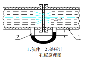
3、 Structure of orifice flowmeter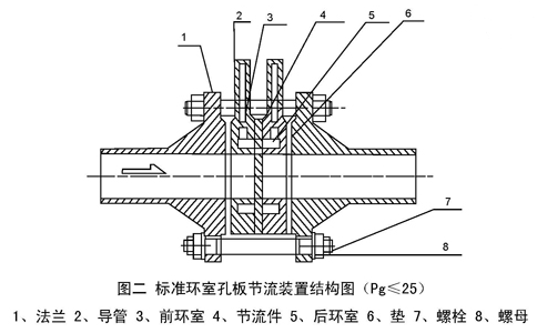
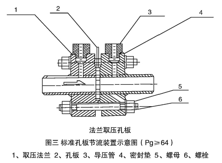
3、 Structural characteristics of orifice flowmeter
1. Ring chamber pressure standard orifice plate
It belongs to the standard orifice plate, and due to the implementation of ring chamber pressure measurement, it improves measurement accuracy and shortens the length of small straight pipe segments required for installation. It can be widely used in various departments.
2. Corner joint drilling pressure standard orifice plate
Belonging to standard orifice plates, this form is commonly used when the pipe diameter exceeds 400 millimeters. The pressure measurement methods are flange drilling, circular pressure equalization, or square pressure equalization ring pressure measurement. The orifice plate can be in the form of a handle orifice plate or a non-standard circular hole plate.
3. Flange pressure gauge standard orifice plate
It belongs to the standard orifice plate, and regardless of the diameter of the pipeline, the centers of the upstream and downstream pressure tapping holes are located 1 hour (25.4mm) away from each end face of the orifice plate. This form is commonly used in refining systems.
4. Radial distance pressure standard orifice plate
It belongs to the standard orifice plate, and the pressure tapping method is pipeline pressure tapping. The center of the upstream pressure tapping hole is located at twice the inner diameter of the pipeline in front of the orifice plate, and the center of the downstream pressure tapping hole is located at half the inner diameter of the pipeline from the rear end face of the orifice plate.
5. Small caliber orifice plate
It is a non-standard orifice plate used for measuring fluids with diameters ranging from 10mm to 50mm.
6. Circular perforated plate
It belongs to non-standard orifice plates and is suitable for measuring the flow rate of fluids that are dirty, have air bubbles, or contain solid particles. Its measurement accuracy is relatively low.
7. Conical inlet orifice plate
Belongs to non-standard orifice plate. The angle between the cone shape and the centerline is 45 degrees, and this cone shape and the inlet orifice plate can be used in situations with very low Reynolds numbers, but the pipe size must not be less than 25 millimeters.


