|
Please provide the following detailed data when placing an order:
(1) The name of the tested medium (2) is high, commonly used, and low flow rate.
(3) Work pressure, working temperature
(4) Medium density and viscosity (water, steam, commonly used gases may not be provided)
(5) Pipeline material, inner diameter, outer diameter
Product Introduction
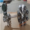
The successful development of V-cone sensors is a qualitative leap in differential pressure flow measurement. It uses a specially designed streamlined conical body installed at the centerline of the pipeline for throttling. Positive pressure PH is taken in the high-speed steady flow zone in front of the cone, and negative pressure PL is taken in the central steady flow zone at the tail of the cone. Within the Reynolds number range of 8 × 10³ to 5 × 10⁶, the flow rate is proportional to the square root of the differential pressure. |
|
| |
Product FeaturesDL-HLG
1. Low installation requirements: front 0-3D straight pipe section, rear 0-1D straight pipe section
2. Range width ratio: usually 10:1, selecting appropriate parameters can achieve up to 50:1
3. Small pressure loss: For the same β value, the pressure loss is 1/3 to 1/5 of the orifice plate
4. Wear resistance: After throttling the streamlined cone, a vacuum layer effect is generated on the surface of the cone, making it less prone to wear
5. Non clogging and non adhesive: The conical thorough blowing design avoids the retention of residues, condensates, or particles in the fluid
6. Good long-term stability: The β value can remain unchanged for a long time and ensure long-term measurement
7. High accuracy: ± 0.5%
8. Good repeatability: better than 0.1%
9. Signal stability: 'Signal fluctuation' is 1/10 of the orifice plate
10. Wide range of beta values: The unique geometric shape of the V-cone flow sensor allows for a wide range of beta values
11. Wide range of pipe diameters: pipe diameter sizes range from 15mm to 2000mm
12. Measurable high temperature and high pressure medium: working temperature up to 850 ℃, high pressure up to 40MPa.
13. Measurable dirty media (coke oven gas, blast furnace gas, raw oil, residual oil, etc.)
14. Measurable gas-liquid two-phase media (moisture, condensate, etc.)
|

|
|
| |
measuring principle
A flowmeter is a differential pressure flowmeter composed of a V-cone sensor and a differential pressure transmitter, which can measure the flow rate of various media within a wide Reynolds number range.
The measurement theory is that due to the viscosity of actual fluids, they are not ideal fluids. When they flow in pipelines, they have two flow states: laminar flow and turbulent flow, under the premise of fully developing the flow inside the pipeline. According to the principle of energy conservation of continuous flow fluid and the Bernoulli equation, for a fluid flowing in laminar flow, its velocity distribution is a parabolic surface symmetrical to the centerline of the pipeline. The pressure drop of the fluid passing through a certain pipeline is proportional to the flow rate; For fluid flowing in turbulent state, its velocity distribution is an exponential surface symmetrical to the centerline of the pipeline, and the pressure drop of the fluid passing through a certain pipeline is proportional to the square of the flow rate.
The V-cone sensor is a V-cone installed in the measuring tube that is coaxial with the centerline of the pipeline. The measuring tube and V-cone of this sensor are designed and precision machined. When the fluid flows through the V-cone in the measuring tube, it re forms a flow state and contracts locally in front of the V-cone. The flow velocity increases, the static pressure decreases, and a pressure difference △ P is generated before and after the V-cone. The high pressure (static pressure) PH is measured at the upstream pipe wall (before fluid contraction), and the low pressure PL (static pressure) is obtained by opening a pressure port at the center axis of the downstream end face of the V-cone, as shown in the following figure: |
|
| |

|
Among them: β - equivalent diameter ratio
ρ - Density under fluid operating conditions
D - Inner diameter of pipeline
K - K coefficient (related to the form of throttling element (beam contraction coefficient), diameter ratio, pressure measurement method, Reynolds number, and pipeline roughness, etc.)
D-diameter at the large cross-section of the V-cone throttling element
ε - coefficient of gas expansion (for incompressible liquids, ε=1)
Qv - volumetric flow rate |
|
Applicable media |
|
1. Gas |
|
Gas: Coke oven gas, blast furnace gas, city gas |
Natural gas: including natural gas with a moisture content of 5% or more |
Various hydrocarbon gases: alkanes, alkenes, and other gases |
Production of various gases: hydrogen, helium, argon, oxygen, nitrogen, etc |
Corrosive gases: wet chloride gases, etc |
Air: including air containing water, dust, compressed air, etc |
Flue gas: flue gas emitted from various boilers and heating furnaces |
|
2. Steam |
|
Saturated steam, superheated steam |
|
3. Liquid |
|
Oil: crude oil, fuel oil, hydrated emulsified oil, diesel, etc |
Water: raw water, drinking water, production water, sewage, etc |
Various aqueous solutions: acid, alkali, saline solution, etc |
Organic chemicals: methanol, ethylene glycol, xylene, etc |
4. Special liquid |
|
Oil+HC gas+sand |
Aerated water: H2O+N2+air; H2O+CO2, etc |
|
| |
|
| |
product type
Connection method: flange (flat welding and butt welding)
Caliber: 15mm-2000mm
Pressure tapping method: socket welding, flange, thread
Pressure: 0-40MPa
Temperature: -40-850 ℃
Material: 304 stainless steel, 316L stainless steel, 20 # carbon steel (see selection table for details)
Application: Liquid, Gas, Steam
Applicable media: Widely used for flow measurement in industries such as municipal, power, chemical, petrochemical, metallurgy, and food processing, almost applicable to all gas and liquid media.

|

|
|
| |
Process parameters required for selection
1. Fluid name
2. Inner and outer diameters of pipelines (mm)
3. Choose the type of V-cone flow sensor
4. Scale flow units (kg/h, t/h, m3/h, Nm3/h)
5. Common traffic, small traffic, large traffic
a. In working condition
b. Under standard conditions (when the medium is gas, the standard flow rate should be specified)
6. Work pressure (MPa)
7. Fluid temperature (℃): high, low, and commonly used temperatures
8. Fluid density (kg/m3)
a. In working condition
b. Under standard conditions (when the medium is a gas, the density value should be specified)
9. Fluid viscosity (Pa · s)
10. Relative humidity
11. Gas composition: Volume percentage (for mixtures of two or more gases)
12. Installation method of sensors
a. Level
b. From bottom to top
13. Pipeline flange
a. According to the flange standard specification, the code is to provide the flange standard and model
b. The second party shall design and provide flange drawings |
remarks:
·To measure water and water vapor, (1), (2), (4), (5), (6), (7), and (12) must be provided
·Measurement of general gases requires the provision of (1) to (13)
·To measure general solutions and oils, (1), (2), (4), (5), (6), (7), (8), (9), (12), and (13) must be provided
·Each data item must be filled with a specific numerical value for the process design, please do not fill in a range of approximately how many. |
be careful!
As the selection of V-cone flowmeter requires professional calculation, please provide us with detailed technical data according to the above requirements, and we will provide you withExcellent solution. |
|
| |
| |
| |

|

|
Wuxi Measurement and Testing Center Liquid Calibration Device |
Installation site of flow meter calibrated by Wuxi Metrology and Testing Center |
|
|