-
E-mail
hualuyb@163.com
-
Phone
18015194111
-
Address
No. 201 Jinhe Road, Jinhu County, Huai'an City, Jiangsu Province
Product Categories
Jiangsu Hualu Instrument Co., Ltd
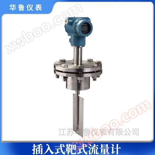
High temperature insertion target flowmeter
NegotiableUpdate on 08/15
- Model
- Nature of the Manufacturer
- Producers
- Product Category
- Place of Origin
Overview
High temperature insertion target flowmeter
Product Details
Detailed Introduction
1、 Product Overview:
The use of capacitive force sensors in high-temperature target flow meters is the key to achieving high precision and stability in this new product. It has changed the various defects of strain gauge target flow meters, such as large temperature drift, poor overload (impact) resistance, and static sealing points. It not only utilizes the original technical advantages of target flow meters, but also has measurement accuracy comparable to volumetric flow meters. In addition to its unique anti-interference and anti impurity performance, it can replace the flow measurement problems that can be measured by conventional flow meters, especially in difficult flow measurement conditions such as small flow rates, high viscosity, easy condensation and blockage, high temperature, low temperature, strong corrosion, and strong vibration, and has good adaptability.
2、 Structure and working principle:
1. Structure:
The high-temperature target flowmeter consists of 1. transmitter head 2. elastic tube sensor 3. target rod 4, target plate 5, and measuring tube. According to different working conditions of the medium, different types of elastic tube sensors, target rods, target plates, and measuring tube structures must be selected. Therefore, users need to provide accurate and complete process parameters, which is crucial for using the instrument well.
2. Working principle:
When the medium flows in the measuring tube, the flowing medium impacts the target plate, causing the target plate to receive an impact force F. The force on the target is transmitted to the elastic tube sensor through the target rod. The size of F is related to the flow velocity V, medium density ρ, and target plate force area A as follows: Target flowmeter
In the formula: F: force acting on the target plate C: resistance coefficient A: force area on the target plate ρ: medium density V2/2g: characteristic flow velocity, where V: medium flow velocity is visible. Under a certain target plate, for a specific medium flow velocity, it is proportional to the square root of the force acting on the target plate. V∝ F。 Therefore, under a certain measurement tube, the medium flow rate Q ∝ F, and the target force received by the elastic tube sensor is proportional to its electrical signal output, the signal is amplified by a preamplifier, and finally converted into a 4-20mA signal output proportional to the medium flow rate through an A/D converter, microprocessor, and D/A converter.
3、 Application scenarios:
High temperature target flowmeter (200~500 ° C) is mainly used for measuring high-temperature fluids, such as steam, thermal oil, emulsified asphalt, heavy oil and other fluid media. It has reliable performance, small temperature drift, and accurate measurement.
4、 Main features:
1. The sensing element has no movable parts and a simple and sturdy structure;
2. The application range and adaptability are very wide. Fluid media in general industrial processes, including liquid, gas, and steam, have a diameter range (DN15 or above) and can be applied in various working states (high, low temperature, normal pressure, high pressure). It can be said that its application range is comparable to that of orifice flow meters.
3. High accuracy, total measurement can reach 0.2% R;
4. Wide range, 4:1-15:1 to 30:1;
5. Can solve difficult flow measurement problems, such as measuring dirty fluids containing impurities (particles); Crude oil, wastewater, high-temperature residual oil, slurry, caustic soda solution, asphalt, etc;
6. High sensitivity, capable of measuring small flow rates, with flow velocities as low as 0.08m/s;
7. Used for fluids with low Reynolds numbers (Red=103-5 × 10³) ranging from DN15 to DN50, it can compensate for situations where standard throttling devices are difficult to apply, such as steam flow measurement;
8. Can adapt to the measurement of high parameter fluids, with pressures up to tens of MPa and temperatures up to 450 ℃;
9. Can be used for measuring bidirectional fluid flow;
10. The pressure loss is relatively low, about half of the standard orifice plate;
11. Strong ability to resist interference from upstream flow blocking components, with a length of 5-10D for the straight pipe section on the upstream side generally sufficient;
12. Dry (hanging weight method) verification can be adopted to facilitate periodic verification for users;
13. Direct reading instruments do not require external energy, are clear and easy to operate, and can also output standard signals (pulse frequency or current signals);
14. The instrument has a high cost performance ratio and is an economical flowmeter;
15. Easy to install and maintain.
5、 Technical parameters:
1. Measurement range 0-400t/h;
2. Accuracy level: 0.5% FS 1.0% FS 2.0% FS;
3. Output signal: 4-20mA two-wire system output is linearly related to flow rate;
4. Power supply voltage: 12-36VDC;
5. Nominal pressure: 1.6 2.5 4.0 6.4MPa;
6. Environmental temperature: -30 ℃~60 ℃ (special: -40 ℃~80 ℃);
7. Medium temperature: ordinary type ≤ 100 ℃ (without heat sink);
High temperature type ≤ 400 ℃ (with heat sink);
8. Liquid receiving material: The measuring chamber is made of carbon steel or 1Cr18i9Ti; The rest is 1Cr18Ni9Ti;
9. Shell material: cast aluminum;
10. Flange standard: DIN2501 special type to be selected by the user;
11. Cable interface: M20 * 1.5 (internal thread);
12. Protection level: IP65;
13. Load characteristics: Maximum load resistance=50 * (power supply voltage -12)=600 Ω @ 24V;
14. Alarm output: collector open circuit form, maximum input current of 100mA, maximum switch voltage of 30VDC, with deviation band control;
15. Pulse output: with a minimum pulse width of 50ms, capable of dual channel output;
16. The maximum cumulative flow display value is 50000 units, automatically reset;
17. Damping time: adjustable from 1 to 100 seconds;
18. Explosion proof form, explosion-proof mark, explosion-proof certificate number.
6、 Installation and usage precautions:
(1) Installation precautions
1. There should be a straight pipe section before and after the measuring tube, and the diameter of the straight pipe section should be equal to the diameter of the flow meter measuring tube. If the diameters are different, a reducer should be used to connect them so that the inlet diameter is the same. The length of the upstream straight pipe section of the flowmeter is generally not less than 6-20D, determined according to different types of upstream flow resistance components, and the downstream straight pipe section is not less than 3-4D. The flowmeter is usually calibrated in a horizontal position and is generally installed in a horizontal pipeline. When it needs to be installed in a vertical pipeline, the hanging weight method must be used to calibrate the vertical installation status of the flowmeter, and the fluid direction should be from bottom to top.
2. For the convenience of maintenance and to prevent one-way force when the flowmeter is activated, a bypass pipeline is installed in parallel. A discharge pipe is installed downstream of the flowmeter to facilitate instrument cleaning and blowing. It is more necessary for measuring dirty fluids or media that are prone to solidification and crystallization. The target plate and measuring tube (body) should be installed coaxially. According to previous tests on a certain caliber, if the center of the target plate deviates 1mm from the center of the pipeline, it may cause a deviation of 1% to 2% in the flow coefficient. However, if the deviation is 1mm from the center of the pipeline, the impact is not significant;
3. When installing an explosion-proof target flowmeter, attention should be paid to checking whether there are explosion-proof markings and explosion-proof certificates, and whether the explosion-proof equipment is intact.
4. For ********** flow meters, due to their small diameter and relatively heavy weight, additional brackets should be installed to support the flow meters in order to prevent pipeline deformation or vibration during operation. For large-diameter flow meters, there is no need to install additional brackets.
(2) Precautions for use
1. Before fluid flow, the downstream valve of the flowmeter should be closed and the upstream valve should be opened to allow fluid to enter the flowmeter section. Then slowly open the downstream valve of the flowmeter and close the bypass valve to allow the fluid to slowly increase. Avoid suddenly opening the valve to impact the target plate and damage the instrument.
2. After long-term operation of the flowmeter, in addition to cleaning the scale on the target plate and measuring tube, the hanging weight method should be used to check whether the characteristics of the force converter have changed. The hanging weight method is to apply a weight gravity in the same direction as the flow at the center of the target plate, adjust the instrument, and apply the force corresponding to the upper limit of the flow meter, which is calculated as F1 according to equation (16.6). Other flow points are added with relevant weights, and the output signal of the instrument is read to check the basic error and linearity of each point. The 'hanging weight method' is described in the manufacturer's product manual or other materials, and can also be referred to.
3. The force exerted by fluid on the target plate is still different from the force exerted by hanging weight, so hanging weight method cannot completely replace real flow calibration. To achieve high accuracy, necessary real flow calibration is still necessary.
4. When copying or modifying the target plate, attention should be paid to the processing accuracy of the target plate, otherwise it will affect the flow coefficient. Experimental data has shown that for a target flowmeter with a diameter of DN=25mm and a target diameter deviation of 0.03mm, the flow coefficient deviation is 1%. The processing accuracy and surface roughness of the target plate also have an impact on the flow coefficient.
5. When the flowmeter is running, if the output value is found to be shaking and the force conversion system is normal, it may be due to the fluid flowing through the target plate and generating vortex streets downstream, causing the target to vibrate under force. It is related to the flow velocity, physical parameters of the medium (density, viscosity), etc. Damping measures can be taken in the force conversion and electrical signal system to improve it.
7、 Fault handling:
The target flowmeter is equipped with a fault self checking program, and users can check some of the reasons through the display screen:
1. When the flow velocity of the measured medium in the pipeline is zero, the instantaneous flow rate value indicated by the flowmeter is not zero. The main reasons for this phenomenon are:
a、 The uneven levelness of the flow meter before and after installation results in the axial horizontal force generated by the tilting of the target plate and target rod, leading to the existence of instantaneous flow rate;
b、 The flowmeter operates for a long time, causing slight changes in the internal stress release of its sensor;
c、 During installation or operation, severe overload causes zero drift;
The above three methods can all refer to the steps and methods for clearing flow meters.
d、 Poor grounding of flowmeter housing;
Solution: The user needs to reconnect to the ground.
e、 The target, target rod, and measuring tool are stuck by debris;
Solution: Close the front and rear valves of the flowmeter, use tools to loosen the connecting bolts between the transition part of the flowmeter and the measuring tube, gently shake the transition part or remove it, clean up debris, and reset it as it is.
2. The abnormal increase in the reading of the flowmeter during operation is mainly caused by:
a、 There are filamentous and strip-shaped impurities hanging on the target film and target rod;
Handling method: Refer to the method for handling miscellaneous items.
b、 Under high blockage conditions, severe blockage occurs between the target plate and the target rod, resulting in an increase in the projected area of the force bearing element target plate along the axis of the measuring tube, that is, a decrease in the annular flow area between the target plate and the measuring tube. As a result, under the same flow rate, the force on the sensor increases, ultimately leading to an abnormal increase in the flow reading;
Solution: Remove the transition component and use tools to remove any debris from the target plate, target rod, and inner wall of the measuring tube.
3. There are many reasons for the large measurement error, and the main reasons are as follows:
a、 During installation, there is a significant misalignment in the concentricity between the flowmeter and the connecting pipeline, and the sealing gasket is not concentric, resulting in the formation of a throttling resistor and greatly affecting the flow state of the measured medium;
Solution: Adjust the installation status.
b、 The straight pipe sections before and after the flowmeter are too short, and elbows, valves, and other components that greatly interfere with the flow state of the measured medium are directly installed in front of the flowmeter;
Solution: Install according to the instructions or perform on-site flow calibration on the flowmeter.
c、 Leakage of bypass pipeline;
Solution: Check and replace the bypass pipeline.
d、 There are strip-shaped debris wrapped around the target, which increases the stress on the target;
Handling method: Refer to the previous method for handling miscellaneous items.
4. There are four main reasons why the flowmeter has no indication or signal:
a、 Poor contact or detachment of power supply;
Solution: For flow meters with built-in batteries, check if the battery is securely installed, if the contacts are in good condition, and if the battery is charged. For external power sources,
It should be checked whether the connections between the connecting wires are intact, whether the wires are conductive, and whether the external power supply is normal.
b、 The flow meter circuit is damaged;
Solution: Return to the factory for repair.
c、 The display screen is damaged;
Solution: Return to the factory for replacement.
d、 User signal receiving system malfunction;
Solution: Check and troubleshoot.
5. The reading of the flowmeter remains zero during operation, and the main reasons for this phenomenon are:
a、 The force bearing component (target) falls off, causing the sensor to be unable to sense;
Solution: Assemble target pieces of the same specifications.
b、 The flowmeter sensor has no voltage output signal;
Solution: First, check if the sensor is damaged. The specific method is to check if there are any changes in the sensor data.
c、 The flow rate of the measured medium is too small, lower than the minimum scale flow rate of the flowmeter;
Solution: Return to the factory and replace the load-bearing components.
8、 Selection precautions:
Target flow meters are suitable for measuring various occasions and media. To ensure satisfactory performance, it is recommended to pay attention to the following items when selecting:
1. Determine the required common traffic and determine the maximum traffic based on 1.5-2.5 times the common traffic.
2. Specify the standards and sealing methods for installing flanges, especially for special installation requirements, which should be clearly stated.
3. When placing an order, the user should specify the medium of the fluid being tested and provide the density of the medium.
4. If you need to measure special media, in addition to using the measuring tube materials provided by the company, you can directly recommend the required measuring tube materials.
9、 Parameter Comparison Table:

Model Selection Table
|
model |
caliber |
Intelligent target flowmeter |
|||||||
|
HL-BSL |
10~5000 |
||||||||
|
|
|
code |
Instrument Type |
|
|||||
|
A* |
Cone tube threaded type |
||||||||
|
A |
Pipeline flange type |
||||||||
|
B |
Clamp on type |
||||||||
|
C |
plug-in |
||||||||
|
D |
Online detachable type |
||||||||
|
E |
other |
||||||||
|
|
code |
Media Type |
|
||||||
|
Y |
liquid |
||||||||
|
Q |
gas |
||||||||
|
Z |
steam |
||||||||
|
|
code |
medium temperature |
|||||||
|
D |
low temperature(-30℃~-200℃) |
||||||||
|
C |
normal temperature(-20℃~+80℃) |
||||||||
|
Z |
Moderate temperature(+80℃~+200℃) |
||||||||
|
G |
high temperature(+200℃~+500℃) |
||||||||
|
nominal pressure |
A:0.6MPa B:1.0MPa C:1.6MPaD:2.5MPa E:4.0MPa F:5.0MPaG:10.0MPa H:15.0MPa I:20.0MPaJ:25.0MPa K:42.0MPa L:2.0MPaM:6.3MPa N:11.0MPa O:16.0MPaP:26.0MPa | ||||||||
|
Compensation form |
P: Pressure compensation |
T: Temperature compensation |
|||||||
|
output form |
N |
No output (built-in lithium battery header display) |
|||||||
|
S |
pulse output |
||||||||
|
R |
Communication output |
||||||||
|
I |
4~20mACurrent output (two-wire system) |
||||||||
|
K |
Alarm switch output |
||||||||
|
G |
GPRSWireless remote transmission |
||||||||
|
Explosion proof structure |
X |
Intrinsically safe type |
|||||||
|
Y |
Explosion proof type |
||||||||
|
Shell Material |
T |
carbon steel |
|||||||
|
N |
stainless steel |
||||||||
|
Q |
Special materials |
||||||||
|
Sensor material |
1 |
Hastelloy alloy |
|||||||
|
|
|
|
|
2 |
titanium |
||||
|
3 |
304stainless steel |
||||||||
|
4 |
Special materials |
||||||||
a、 The specifications of the flowmeter flange shall comply with the relevant technical parameters, technical conditions, and types specified in the GB/T series standards. It can also be processed according to customer requirements;
b、 In the selection of flow meters, users should specify the various requirements of the required flow meter in the format of the model description;
c、 If users need to use calibers, nominal pressures, and output forms other than those specified in this model, please provide explanations;
d、 When selecting a high-temperature flowmeter, in addition to filling in the model description format, the high operating temperature of the tested medium should be specifically indicated;
e、 For flow meters with temperature and pressure compensation, in addition to filling in the model description format, the operating temperature and pressure range that need to be compensated should be specifically stated;
f、 Users need special measurement tube materials, which should be explained.