- Phone
-
Address
No. 6, Lane 1118, Jintong Road, Putuo District, Shanghai
Product Categories
Shanghai Kangdeng Electric Technology Co., Ltd
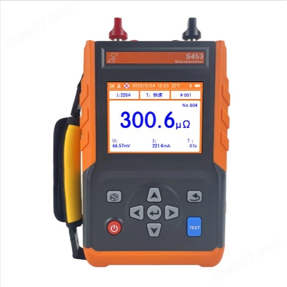


Handheld circuit resistance tester
NegotiableUpdate on 05/13
- Model
- Nature of the Manufacturer
- Producers
- Product Category
- Place of Origin
Overview
Handheld circuit resistance tester, with high-speed microcontroller as the core, built-in rechargeable lithium battery and charging circuit, combined with high-precision A/D converter and programmable current source technology, can achieve high-precision, high stability measurement effect and highly automated measurement function. In terms of circuit design, it has overheat protection circuit design, ensuring safety performance.
Product Details
Handheld circuit resistance testerIt is an intelligent and user-friendly comprehensive testing instrument specially developed by our company for measuring resistance,haveself-check、High output current、Measure width、Strong anti-interference ability and other characteristicsIt also has the advantages of rapid measurement, high measurement accuracy, simple operation, small size, light weight, and easy portability.5.6-inch color LCD display, high resolution, bilingual operation interface in Chinese and English, simple button design for easy operation, clear and concise interface.This instrument adopts new power technology and is built-inLarge capacity rechargeable lithium batteryCan continuously output high current for a long time; Multiple operating currents are available to meet different resistance measurement needs, with a maximum testing time of up to60 seconds; Design protection functions such as open circuit protection and overheating protection, with good safety performance; Adopting fully digital measurement technology and anti power frequency interference technology, it can accurately measure even in strong interference environments; Handheld appearance design, small size, easy to carry, especially suitable for on-site applications; Large data storage capacity, convenient for data collection; Optional printer, can be used for data printing.
Handheld intelligent circuit resistance tester,at high speedmicrocontrollercore,Built in capabilityCharging lithium batteriesAnd charging circuitCombined with high precisionA/D converterAnd programmable controlcurrent sourcetechnologycan reachhigh precision、high stabilityThe measurement effect of sex and highly automated measurement function,In the circuitdesignIn terms of aspects, withThere is overheatingprotectCircuit design ensures safety performance.
Circuit resistance tester,Also known as contact resistance tester,Suitable for directly measuring the grounding resistance of various grounding devices and high-precision measurement of high-voltage switch contact resistance. It can also be used for micro ohm resistance measurement and is suitable for measuring various electrical equipment、Grounding resistance of lightning rods and other grounding equipment.
Handheld circuit resistance testermodel
type number |
Maximum test current |
Test line quality |
KDS452 |
The maximum test current can reach100A |
A 3-meter test line is approximately 2.7kg 5-meter test line weighs approximately 8.0kg |
KDSS453 |
The maximum test current can reach220A |
A 3-meter test line is approximately 2.7kg 5-meter test line weighs approximately 8.0kg |
Handheld circuit resistance testerTechnical Specifications
merit can |
Measurement of switch contact resistance, loop resistance, contact resistance, and micro ohm resistance |
|
electricity source |
built-in:12.6V 9000mAh rechargeable lithium battery; |
|
test method |
Four line method |
|
charge electricity device |
12.6V/2A charger |
|
display mode |
5.6-inch industrial grade high brightness color LCD screen |
|
test interface |
I+(positive current), I - (negative current), U+(positive voltage), U - (negative voltage) |
|
output current |
≤5AThe10AThe30AThe50AThe80AThe100AThe200AThe220A |
|
|
quantity Cheng (Built in battery) |
≤5A : |
1. Mu.. Omega..~3500mΩ |
10A : |
0.1 μ Omega~200mΩ |
|
30A : |
0.1 μ Omega~20mΩ |
|
50A : |
0.01 μ Omega~15mΩ |
|
80A : |
0.01 μ Omega~10mΩ |
|
100A : |
0.01 μ Omega~5mΩ |
|
200A: |
0.01 μ Omega~500uΩ |
|
220A : |
0.01 μ Omega~500uΩ |
|
minimumresolution |
0.01 μ Omega |
|
Step current |
Yes, step value2.5A |
|
test accuracy |
electric current:30A~220A ± (reading x 0.1%+range 0.2%+1 μ Ω) electric current:10Aor≤5A± (reading x 0.5%+range 0.2%+10 μ Ω) |
|
hit India machine |
Yes (optional), press the print button to print the test results |
|
data storage |
Automatically save data after testing is completed, loop save, can store up to999 sets of data |
|
Instrument size |
about188mm (length) x 85mm (width) x 312mm (height) |
|
outer packaging dimensions |
about546mm (length) x 392mm (width) x 193mm (height) |
|
quality quantity |
Instrument quality: approximately2.2kg |
|
measure try line |
currentVoltageTwo end tap test line, simple wiring, resistance less than10mΩ |
|
Test time |
≤100A:fast(Recommended), 10s, 20s, 30s, 40s, 50s, 60s ≥100A:fast |
|
change block |
≤5AThe10AThe30AThe50AThe80AThe100AThe200AThe220A |
|
Data deletion |
Select the Format Memory option in the settings interface toDelete all data |
|
data lookup |
Enter the data search interface and press the up, down, left, and right keys to browse throughStoreddata |
|
Auto Shutdown |
When using battery power, if there is no operation after turning on the device5Automatically shut down in minutes |
|
battery voltage |
There is a battery level indicator in the upper right corner of the instrument panel. When the symbol is displayed“ |
|
back light |
The backlight can be set to three brightness levels: high, medium, and low |
|
operating current |
The working current in non test state is230mA |
|
The working current in the testing state can be set by oneself | ||
circuit protection |
Equipped with wire breakage protection, overheating protection, etc |
|
Operating Temperature |
Temperature monitoring is installed inside the instrument |
|
Working temperature and humidity |
-10℃~50℃; Below 90% RH, no condensation |
|
Storage temperature and humidity |
-10℃~60℃; Below 70% RH |
|
charging voltage |
12.6V |
|
Suitable for safety regulations |
IEC61010-1, CAT Ⅲ 600V, Pollution Level 2, JJG724-1991 "Verification Regulations for DC Digital Ohmmeters", JJG166-1993 "Verification Regulations for DC Resistors", "DL/T967-2005 Verification Regulations for Loop Resistance Testers and DC Resistance Rapid Testers" |
|
Handheld circuit resistance testerstructure
H~]`ZITY)S`B3.png")
1. cooling fan 2. Dedicated charger portrotundity
3. U+terminal 4. I+terminal
5. I-terminal 6. U-terminal
7. Print key 8. power button
9. Up, down, left, right, and confirm keys 10. TEST key
11. back button 12. LCD screen
13. carrying strap
Intelligent handheld circuit resistance tester for testingtrywiring
The dedicated test lines are clamped to the output terminals of the tested products. Check if there is an oxide layer on the clamped surface of the test sample lead out end. If there is, the oxide layer should be cleaned first before clamping, otherwise it will affectmeasuretryAccuracy. The testing pliers should ensure a firm and reliable connection to prevent them from falling off during the testing process. Connect the other end of the test line to the red and black terminals of the instrument according to the color.
Connect the grounding terminal to the ground with a grounding wire, and connect the I+, I -, U+, U - terminals to the test sample using the four wire method shown in the following figure.

Important Notice:
1. Type differentiation of I+/I - current output terminals, S452 maximum output 100A, S453 maximum output 220A, U+/U - voltage input socket, maximum input 20V. In order to simplify and facilitate the testing wiring, the dedicated testing line that comes with the instrument is a two end tap. The thick wire of each testing line is connected to the current terminal, and the thin wire is inserted into the voltage socket to connect the current and voltage wires to the same testing end. I+/U+is connected to one end of the circuit resistor, and I -/U - is connected to the other end. I+/U+and I -/U - can be exchanged. It is necessary to use a dedicated low resistance test wire that comes with the instrument, tighten the current terminal, and firmly clamp the test clip to reduce lead resistance and save battery power.
If there is poor contact between I+/U+or I -/U - and the current cannot reach the set value, the instrument will stop testing and display "poor contact of test line".
}L3[NO`{EC.png")
3. In a live environment, it is necessary to ensure that one end of the test sample is grounded, otherwise one of U+or U - should be grounded.
4.If a high current (100A or above) is used for a long time for measurement, it will cause the temperature of the instrument equipment to rise. The test will continue and measurement data can be obtained, but it will prompt to display "temperature too high".

5. If using high current for a long time(100A以上)Measurement, and the interface keeps displaying 'temperature too high'In this case, continuing the testing will triggersendDevice overheating protection mechanism, the device will stop outputting.

6The charging socket (12.6V) should use a specialized lithium battery charger with a charging voltage of 12.6V. The charger has a charging indicator light, which is red to indicate charging and turns green when fully charged. Using a 2A charger, the charging time is about 3 hours. If the meter is not used for a long time, it should maintain a reserve of about 50% of electricity and be charged and discharged regularly. The battery level should be checked once a month, and if it is low, it should be charged promptly.
(2)measuretryoperation
|
When connecting the test clamp to the grounding wire, be careful that the contact end is exposed to the air for a long time and covered with an oxide film on the surface. This oxide film may cause unstable or inaccurate test results. Therefore, when wiring, pay attention to cleaning the oxide film, or after connecting the test clamp to the lead out terminal, twist the test clamp vigorously a few times to cut through the oxide film to ensure good contact. |
If there is a sudden automatic shutdown during the testing process, it may be caused by insufficient battery. In this case, it is necessary to connect a charger for charging or set the output current below 5A for emergency testing. |
Before testing, first determine the current gear (≤ 5A, 10A, 30A, 50A, 80A, 100A, 200A, 220A), time (fast (recommended), 10S, 20S, 30S, 40S, 50S, 60S (200A, 220A only fast)), and sample number (000-999). In the testing interface, press“![]() ”Or“
”Or“![]() ”Move the cursor with the key to select: current setting, test time, sample number, press“
”Move the cursor with the key to select: current setting, test time, sample number, press“![]() ”Or“
”Or“![]() ”The key settings correspond to the parameters. If the parameters are set incorrectly, it will affect the test results. When setting the current, please refer to the range settings in the technical specifications and set different current levels according to different power supply schemes and the measured resistance values.
”The key settings correspond to the parameters. If the parameters are set incorrectly, it will affect the test results. When setting the current, please refer to the range settings in the technical specifications and set different current levels according to different power supply schemes and the measured resistance values.
After setting up, long press“![]() ”Start testing with the key. At the beginning of the test, it displays "testing in progress...", and after the test is completed, the resistance value of the test is displayed. If the tested resistance exceeds the rangeDisplay '-- OL --'.
”Start testing with the key. At the beginning of the test, it displays "testing in progress...", and after the test is completed, the resistance value of the test is displayed. If the tested resistance exceeds the rangeDisplay '-- OL --'.
If you need to interrupt the test during the testing process, you can short press“![]() ”Key interrupt.
”Key interrupt.
Suggest using 'fast' to save battery power.When selecting fast or 10-50 seconds, you can press at any time during the process“![]() ”Key abort. This method can effectively overcome the influence of unstable thermoelectric potential in the measurement circuit, with good accuracy, and can reduce power consumption and instrument temperature rise.
”Key abort. This method can effectively overcome the influence of unstable thermoelectric potential in the measurement circuit, with good accuracy, and can reduce power consumption and instrument temperature rise.
Usage 100AWhen in gear, try not to choose a 60 second test time because this method consumes a lot of power. After completing a measurement, the instrument needs to cool down for more than 10 minutes before starting the measurement again. Otherwise, it may cause the instrument to overheat protection, display "temperature too high", and trigger overheating protection. If there is no need to run for 60 seconds, you can press at any time“![]() ”Press the key to abort and display the measurement data.
”Press the key to abort and display the measurement data.
(3) Self inspection
Users can use the self checking resistor provided with the instrument to perform self checking tests. If the resistance value tested by the instrument is consistent with the standard resistance value, it indicates that the instrument circuit resistance test function is normal.
(4)Protective measures for instruments
In order to protect the safety of operators and equipment, this instrument is equipped with several protective measures such as high temperature protection and low battery level.
Similar Product Recommend


