-
E-mail
2851676109@qq.com
-
Phone
13382303480
-
Address
No. 19 Runlou Road, Dailou Concentrated Industrial Zone, Huai'an City, Jiangsu Province
Product Categories
Jiangsu Hongqi Automation Equipment Co., Ltd

HQLWGY sanitary clamp turbine flowmeter
NegotiableUpdate on 06/06
- Model
- Nature of the Manufacturer
- Producers
- Product Category
- Place of Origin
Overview
Brief introduction: HQ-LWGY sanitary clamp type turbine flowmeter is a new generation turbine flowmeter with the characteristics of simple structure, lightweight, high accuracy, good reproducibility, sensitive response, easy installation, maintenance and use. It is widely used for measuring closed pipelines and stainless steel 1Cr1
Product Details
Brief introduction:
The HQ-LWGY sanitary clamp type turbine flowmeter is a new generation of turbine flowmeter with the characteristics of simple structure, lightweight, high accuracy, good reproducibility, sensitive response, and easy installation, maintenance, and use. It is widely used to measure closed pipelines and does not corrode stainless steel 1Cr18Ni9Ti, 2Cr13, corundum Al2O3, hard alloys, and has no impurities such as fibers or particles.
HQ-LWGY sanitary clamp turbine flowmeter
1、 Overview of HQ-LWGY Sanitary Clamp Turbine Flow Meter
HQLWGY sanitary clamp turbine flowmeter is a precision measuring instrument that adopts advanced microprocessing technology. It has the characteristics of strong functionality, wide flow range, simple operation, and easy installation and use. Turbine flow meters widely used in the fields of petroleum, chemical, metallurgical, scientific research, etc., equipped with sanitary fittings, are mostly used in the pharmaceutical industry. The products have the following advantages:
1. Low pressure loss, impeller with anti-corrosion function
2. Can display on-site, instantaneous flow rate, cumulative total amount
3. The whole machine has low power and can work for a long time with the internal battery, making it an ideal passive display instrument
4. Using EEPROM for power down protection of cumulative flow meter coefficients, with a protection time greater than 10 years
2、 Structure and working principle of HQ-LWGY sanitary clamp turbine flowmeter
2.1 Structure
The structure of the sensor is shown in Figure 1, which mainly consists of a housing, a front guide frame, an impeller, a rear guide frame, a clamping ring, and a magneto electric induction converter with an amplifier.
2.2 Working principle
When the measured fluid flows through the sensor, the impeller inside the sensor rotates with the help of the kinetic energy of the fluid, and the impeller is the magnetoresistance in the periodic electromagnetic induction system. Periodically changing the magnetic flux passing through the coil to generate an electrical pulse signal, which is amplified by an amplifier and transmitted to the corresponding flow integrator for flow or total measurement.
3、 Main technical parameters of HQ-LWGY sanitary clamp turbine flowmeter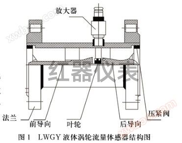
1. Measurement range of sanitary clamp turbine flowmeter:
|
Instrument caliber (mm) |
Normal traffic Range m3/h |
Expand traffic Range m3/h |
Conventional stress tolerance MPa |
Zui high stress tolerance MPa |
|
DN 4 |
0.04-0.25 |
0.04-0.4 |
6.3 |
32 |
|
DN 6 |
0.1-0.6 |
0.06-0.6 |
6.3 |
32 |
|
DN 10 |
0.2-1.2 |
0.15-1.5 |
6.3 |
32 |
|
DN 15 |
0.6-6 |
0.4-8 |
6.3 |
32 |
|
DN 20 |
0.8-8 |
0.45-9 |
6.3 |
32 |
|
DN 25 |
1-10 |
0.5-10 |
6.3 |
32 |
|
DN 32 |
1.5-15 |
0.75-15 |
6.3 |
32 |
|
DN 40 |
2-20 |
1-20 |
6.3 |
32 |
|
DN 50 |
4-40 |
2-40 |
2.5 |
25 |
|
DN 65 |
7-70 |
3.5-70 |
2.5 |
25 |
|
DN 80 |
10-100 |
5-100 |
1.6 |
25 |
|
DN 100 |
20-200 |
10-200 |
1.6 |
16 |
|
DN 125 |
25-250 |
12.5-250 |
1.6 |
16 |
|
DN 150 |
30-300 |
15-300 |
1.6 |
16 |
|
DN 200 |
80-800 |
40-800 |
1.6 |
16 |
2. Electrical performance indicators
Working power supply: External power supply:+24VDC
Internal power supply: 3.6V lithium battery (lithium battery can be used for more than two years)
Output mode: Pulse signal 4~20mA current signal, corresponding to flow rate 0~Qmax, 20mA corresponding flow rate can be set by the user themselves. RS485 communication: capable of transmitting instantaneous and cumulative traffic, as well as time and date
3. Explosion proof mark: Exd Ⅱ BT4
4. Protection level: IP65
4、 Dimensions and Installation of HQ-LWGY Sanitary Clamp Turbine Flow Meter

4、 Dimensions and Installation of HQ-LWGY Sanitary Clamp Turbine Flow Meter
Note: Flange connection size: in accordance with GB/T9119-2000 standard
Installation of HQ-LWGY Sanitary Clamp Turbine Flow Meter
1. Installation location
The flowmeter should operate under conditions where the temperature of the measured liquid is -20~+120 ℃ and the relative humidity of the environment is not greater than 80%. From the perspective of maintenance convenience, it should be installed in a location that is easy to disassemble and replace, and avoids the impact of piping vibration or stress. Considering the protection of the amplifier, efforts should be made to avoid exposing it to strong thermal radiation and radioactivity. At the same time, it is necessary to avoid the influence of external strong electromagnetic waves on the detection coil. If it cannot be avoided, a shielding cover should be added to the amplifier of the sensor, otherwise interference will seriously affect the normal operation of the display instrument.
2. Installation location
The flowmeter should be installed horizontally, and the arrow indicating the flow direction on the sensor should match the direction of fluid flow during installation.
3. Key points of piping
(1) In order to mitigate the impact of liquid vortex and uneven cross-sectional flow velocity on measurement, necessary straight sections or rectifiers should be installed at the inlet and outlet of the sensor. Generally, the straight pipe section of the upstream part (inlet) is required to be (15-20) D (D is the nominal diameter of the sensor) The downstream part (the length of the straight pipe section at the outlet is 5D), while the diameter of the straight pipe and the sensor are connected
In addition, the length of the upstream straight pipe section should be determined based on the status of the piping in front of the sensor. Generally, the recommended length is as follows (see Figure 4)
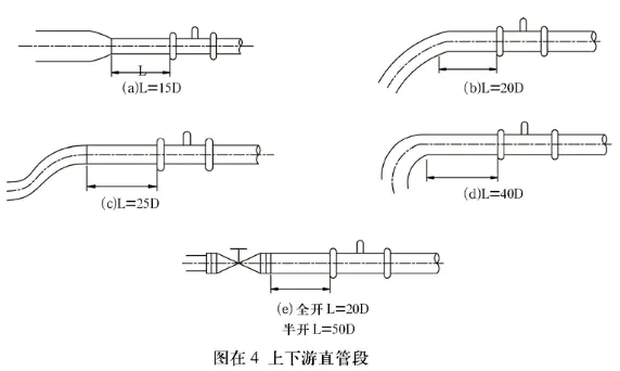
When tuning contraction: L=15D for single bend pipe joint: L=20D
When double bent pipe joint: L=25D (one plane) L=30D (two planes)
When using a right angled bend joint: L=40D
When there is a straight stop valve: L=20D (valve fully open)
L=50D (valve half open)
Additionally. In order to achieve more effective eddy currents and improve measurement accuracy, a rectifier composed of a bundle of conduits can be inserted into the straight pipe section of the upstream section. In French, the length of the straight pipe section upstream of the rectifier is (10~20) D.
(2) In order to ensure the normal operation of the sensor and improve its lifespan, a filter with a mesh size of 3-9 days/cm2 should be installed on the pipeline in front of the sensor to remove impurities in the flow. In general, the mesh with a larger diameter is sparse, while the mesh with a smaller diameter is dense. To ensure the normal operation of the sensor, a filter should also be selected according to the actual usage situation.
(3) When welding the inlet flange of the sensor, it is necessary to pay attention to the absence of protruding parts inside the pipe. When connecting the inlet flange, the outer edges of the two flanges should be completely aligned, and the ring should not be exposed inside the tube. Eccentric reducing joints will cause uneven distribution of flow velocity, so they cannot be used.
(4) In order to ensure the maintenance needs under the working diameter, cut-off valves (globe valves) should be installed on the front and rear pipelines of the transmitter, and bypass pipelines should also be set up.
The flow control valve should be installed downstream of the sensor. When using the sensor, the upstream shut-off valve must be fully opened to avoid turbulence in the upstream fluid.
(5) When the flow rate through the sensor exceeds the upper limit of the flow range, the bearing will wear faster due to high speed. For this reason, when excessive flow is expected, the flow control valve installed in the downstream section can be used to regulate the flow.
(6) Due to the significant measurement error caused by the gas in the pipeline, special attention should be paid to the presence of gas in the measured liquid during installation, especially for the measurement of light liquid media, which must be equipped with an air separator. The piping from the air separator to the sensor should be installed at an upward tilt to allow gas to accumulate here. In addition, attention should be paid to the control of downstream back pressure of the sensor. The magnitude of the back pressure can be calculated according to the following formula: Pa ≥ △ P+1.25Pv
In the formula: Pa - downstream back pressure:
The pressure loss of the sensor at high flow rates;
The saturated vapor pressure of the medium at high operating temperatures for Pv zui.
(7) When installing sensors on a new pipeline, to avoid impurities from entering the sensor, an empty pipe should be used instead of the sensor. After running for a period of time, it should be confirmed that the impurities have been eliminated before replacing the sensor.
(8) When installing sensors with nominal pressures of PN16 and 25Mpa, a small amount of lubricating oil should be applied to the cold cutting edge of the sleeve, the thread of the nut, and various contact parts. The nut and sleeve should be sequentially fitted onto the pipe, and then the pipe should be inserted into the bottom of the tapered hole of the sensor housing. Place the sleeve in place, and while tightening the nut, rotate the pipe until it stops moving, and then tighten the nut 1-11/3 turns.
5、 Ordering Instructions for HQ-LWGY Sanitary Clamp Turbine Flow Meter
When ordering this product, users should pay attention to selecting appropriate specifications based on the nominal diameter of the pipeline, flow range, nominal pressure, maximum pressure of the medium, temperature range of the medium, and environmental conditions. Explosion proof grade requirements must be indicated for use in hazardous areas.
Flow meters are generally of the basic type with pulse output for operating conditions. If other accessories and output functions are required, please specify them when placing an order. When placing an order, please fill in the following format in detail and correctly.
Selection of HQ-LWGY Sanitary Clamp Turbine Flow Meter
|
HQLWGY□
|
□□□
|
□
|
□
|
□
|
speak bright
|
|
|
class
type
|
HQLWGY
|
|
|
|
|
Basic type,+5-24DCVPower supply,
|
|
HQLWGB
|
|
|
|
|
4~20mATwo wire current output, remote transmission type
|
|
|
HQLWY
|
|
|
|
|
Battery powered on-site display type
|
|
|
HQLWYA
|
|
|
|
|
local display/4~20mA Two wire current output
|
|
|
state-owned
call
open up or clear out by poking or jabbing
footpath
|
4
|
|
|
|
4mm, ordinary turbine flow range0.04~0.25m3/h
Wide range turbine is0.04~0.4m3/h
|
|
|
6
|
|
|
|
6mm, ordinary turbine flow range0.1~0.6m3/h
Wide range turbine is0.06~0.6m3/h
|
||
|
10
|
|
|
|
10mm, ordinary turbine flow range0.2~1.2m3/h
Wide range turbine is0.15~1.5m3/h
|
||
|
15
|
|
|
|
15mm, ordinary turbine flow range0.6~6m3/h
Wide range turbine is0.4~8m3/h
|
||
|
25
|
|
|
|
25mm, ordinary turbine flow range1~10m3/h
Wide range turbine is0.5~10m3/h
|
||
|
40
|
|
|
|
40mm, ordinary turbine flow range2~20m3/h
Wide range turbine is1~20m3/h
|
||
|
50
|
|
|
|
50mm, ordinary turbine flow range4~40m3/h
Wide range turbine is2~40m3/h |
||
|
80
|
|
|
|
80mm, ordinary turbine flow range10~100m3/h
Wide range turbine is5~100m3/h
|
||
|
100
|
|
|
|
100mm, ordinary turbine flow range20~200m3/h
Wide range turbine is10~200m3/h
|
||
|
150
|
|
|
|
150mm, ordinary turbine flow range30~300m3/h
Wide range turbine is15~300m3/h
|
||
|
200
|
|
|
|
200mm, ordinary turbine flow range80~800m3/h
Wide range turbine is40~800m3/h
|
||
|
provide against
burst
|
|
|
|
Unmarked, non explosion proof type
|
||
|
B
|
|
|
Explosion proof type
|
|||
|
accuracy
grade
|
A
|
|
accuracy0.5level
|
|||
|
B
|
|
accuracy1level
|
||||
|
turbine
type
|
A
|
Wide range turbine
|
||||
|
B
|
Ordinary turbine
|
|||||
|
HQLWGY□
|
□□□
|
□
|
□
|
□
|
say bright
|
|
|
class
type
|
HQLWGY
|
|
|
|
|
Basic type,+5-24DCVPower supply,
|
|
HQLWGB
|
|
|
|
|
4~20mATwo wire current output, remote transmission type
|
|
|
HQLWY
|
|
|
|
|
Battery powered on-site display type
|
|
|
HQLWYA
|
|
|
|
|
local display/4~20mA Two wire current output
|
|
|
common
call
open up or clear out by poking or jabbing
footpath
|
4
|
|
|
|
4mm, ordinary turbine flow range0.04~0.25m3/h
Wide range turbine is0.04~0.4m3/h
|
|
|
6
|
|
|
|
6mm, ordinary turbine flow range0.1~0.6m3/h
Wide range turbine is0.06~0.6m3/h
|
||
|
10
|
|
|
|
10mm, ordinary turbine flow range0.2~1.2m3/h
Wide range turbine is0.15~1.5m3/h
|
||
|
15
|
|
|
|
15mm, ordinary turbine flow range0.6~6m3/h
Wide range turbine is0.4~8m3/h
|
||
|
25
|
|
|
|
25mm, ordinary turbine flow range1~10m3/h
Wide range turbine is0.5~10m3/h
|
||
|
40
|
|
|
|
40mm, ordinary turbine flow range2~20m3/h
Wide range turbine is1~20m3/h
|
||
|
50
|
|
|
|
50mm, ordinary turbine flow range4~40m3/h
Wide range turbine is2~40m3/h |
||
|
80
|
|
|
|
80mm, ordinary turbine flow range10~100m3/h
Wide range turbine is5~100m3/h
|
||
|
100
|
|
|
|
100mm, ordinary turbine flow range20~200m3/h
Wide range turbine is10~200m3/h
|
||
|
150
|
|
|
|
150mm, ordinary turbine flow range30~300m3/h
Wide range turbine is15~300m3/h
|
||
|
200
|
|
|
|
200mm, ordinary turbine flow range80~800m3/h
Wide range turbine is40~800m3/h
|
||
|
provide against
burst
|
|
|
|
Unmarked, non explosion proof type
|
||
|
B
|
|
|
Explosion proof type
|
|||
|
accuracy
grade
|
A
|
|
accuracy0.5level
|
|||
|
B
|
|
accuracy1level
|
||||
|
turbine
type
|
A
|
Wide range turbine
|
||||
|
B
|
Ordinary turbine
|
|||||


