-
E-mail
maike168@126.com
- Phone
-
Address
Jinhui Industrial Park, Fengxian District, Shanghai
Product Categories
Shanghai Maike Pump Manufacturing Co., Ltd

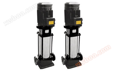
GB type detachable pipeline pump
NegotiableUpdate on 11/10
- Model
- Nature of the Manufacturer
- Producers
- Product Category
- Place of Origin
Overview
The GB type detachable pipeline pump is a novel and technologically advanced product developed on the basis of the ISG type pump. This vertical pump has made bold breakthroughs in its overall structure design. Adopting an independent bearing body and pump shaft support, the shortcomings of the original vertical pump relying on motor bearings for support have been solved; Adopting an excellent hydraulic model impeller eliminates the shortcomings of the original vertical pump with high axial force; The motor adopts the Y series standard universal motor, which solves the problem of difficult replacement of the original vertical pump extension shaft motor; At the same time, the 100% detachable structure solves the problem of replacing the bearings, mechanical seals, impellers, and pump shafts of high-power water pumps. Compared with similar domestic products, this pump has irreplaceable advantages such as smoother operation, longer service life, more convenient matching, and easier maintenance. Among the vertical pump series products, it ranks among the top in China with advanced technologies. It is an ideal product to replace various conventional centrifugal pumps such as ISG vertical pumps, IS centrifugal pumps, and S-type double suction pumps.
Product Details
Product Features:
- The GB type detachable pipeline pump has a vertical structure, which is easy to install and debug. The uniquely designed motor and pump body are connected by a coupling body, with high concentricity and processing accuracy, greatly reducing the footprint and reducing the construction investment of the pump room by 30% to 60%. The stable foundation, compact structure, exquisite casting and appearance treatment give the vertical centrifugal pump a new beauty, making the produced product radiate artistic charm, comparable to famous foreign manufacturers' vertical pumps.
- Equipped with Y series standard universal motors produced by well-known domestic manufacturers, it runs smoothly and has extremely low noise.
- The bearings adopt internationally renowned brand precision bearings, which have high precision, good reliability, and long service life.
- The impeller adopts an excellent hydraulic model from the 1990s that can self balance axial force, greatly extending the service life of pump bearings and mechanical seals.
- The bearings inside the motor bearing seat are equipped with oil filling holes and oil drainage holes, making maintenance and upkeep of the bearings very convenient.
- The detachable rigid intermediate coupling ensures that the pump starts without vibration or noise, and the rotating parts are equipped with reliable safety protection covers, providing excellent safety.
- Mechanical seals are made of materials such as stainless steel, tungsten carbide, and fluororubber, which are resistant to high temperatures and pressures, have a long operating life, no leakage, and no wear on the shaft, ensuring a clean working environment.
- The pump cover structure is uniquely designed, and the bearing seat can be easily removed by simply removing the hard middle coupling and pump cover nut. Pump cover, pump shaft, impeller and other components can be replaced with mechanical seals and impellers without disassembling the motor, pump body and pipeline, making maintenance convenient and fast.
Working conditions:
- The high working pressure of the pump system is 1.6MPa, which means that the pump suction pressure+pump head is ≤ 1.6MPa (if the pump head and working pressure are greater than 1.6MPa, they should be separately specified in the order, so that the overcurrent components and connecting components of the pump can be made of cast steel during manufacturing).
- The conveying medium is clear water or other liquids with physical and chemical properties similar to clear water. (If the conveying medium contains small particles, it should be specified separately when ordering to facilitate the assembly of wear-resistant mechanical seals.).
- Environmental temperature ≤ 40 ℃, relative humidity ≤ 95%.
performance parameters
| Model number | Traffic volume Q |
head H |
speed n |
efficiency or |
Supporting power P | cavitation Excess NPSH |
Vortex chamber Form |
Pump inlet and outlet Caliber φ |
|
| m3/h | L/S | m | r/min | % | KW | m | mm | ||
| 40GB-18 | 5.00 | 1.39 | 18 | 2950 | 55 | 1.5 | 2.2 | Single vortex chamber | 40×40 |
| 40GB-20 | 5.00 | 1.39 | 20 | 2950 | 56 | 1.5 | 2.2 | Single vortex chamber | 40×40 |
| 40GB-25 | 5.00 | 1.39 | 25 | 2950 | 44 | 1.5 | 2.2 | Single vortex chamber | 40×40 |
| 40GB-32 | 5.00 | 1.39 | 32 | 2950 | 43 | 2.2 | 2.2 | Single vortex chamber | 40×40 |
| 50GB-18 | 12.5 | 3.47 | 18 | 2950 | 53 | 1.5 | 2.5 | Single vortex chamber | 50×50 |
| 50GB-20 | 12.5 | 3.47 | 20 | 2950 | 54 | 2.2 | 2.5 | Single vortex chamber | 50×50 |
| 50GB-25 | 25 | 6.95 | 25 | 2950 | 55 | 3 | 2.5 | Single vortex chamber | 50×50 |
| 50GB-32 | 12.5 | 3.47 | 32 | 2950 | 56 | 3 | 2.5 | Single vortex chamber | 50×50 |
| 65GB-25 | 25 | 6.95 | 25 | 2950 | 64 | 4 | 2.5 | Single vortex chamber | 65×65 |
| 65GB-32 | 25 | 6.95 | 32 | 2950 | 65 | 5.5 | 3 | Single vortex chamber | 65×65 |
| 80GB-18 | 50 | 13.9 | 18 | 2950 | 62 | 4 | 3 | Single vortex chamber | 80×80 |
| 80GB-20 | 50 | 13.9 | 20 | 2950 | 65 | 4 | 3.5 | Single vortex chamber | 80×80 |
| 80GB-25 | 50 | 13.9 | 25 | 2950 | 63 | 5.5 | 3.5 | Single vortex chamber | 80×80 |
| 80GB-32 | 50 | 13.9 | 32 | 2950 | 66 | 7.5 | 3.5 | Single vortex chamber | 80×80 |
| 80GB-45 | 50 | 13.9 | 45 | 1450 | 62 | 11 | 3.5 | Single vortex chamber | 80×80 |
| 80GB-50 | 50 | 13.9 | 50 | 1450 | 64 | 15 | 3.5 | Single vortex chamber | 80×80 |
| 80GB-75 | 50 | 13.9 | 75 | 2950 | 63 | 22 | 3.5 | Single vortex chamber | 80×80 |
| 80GB-80 | 50 | 13.9 | 80 | 2950 | 63 | 22 | 3.5 | Single vortex chamber | 80×80 |
| 80GB-95 | 50 | 13.9 | 95 | 1450 | 55 | 30 | 3.5 | Single vortex chamber | 80×80 |
| 80GB-100 | 50 | 13.9 | 100 | 1450 | 53 | 30 | 3.5 | Single vortex chamber | 80×80 |
| Model number | Traffic volume Q |
head H |
speed n |
efficiency or |
Supporting power P | cavitation Excess NPSH |
Vortex chamber Form |
Pump inlet and outlet Caliber φ |
|
| m3/h | L/S | m | r/min | % | KW | m | mm | ||
| 80GB-115 | 50 | 13.9 | 115 | 2950 | 53 | 37 | 3.5 | Single vortex chamber | 80×80 |
| 80GB-120 | 50 | 13.9 | 120 | 2950 | 54 | 45 | 3.5 | Single vortex chamber | 80×80 |
| 80GB-125 | 50 | 13.9 | 125 | 2950 | 54 | 45 | 3.5 | Single vortex chamber | 80×80 |
| 100GB-18 | 100 | 27.8 | 18 | 2950 | 64 | 7.5 | 3.5 | Single vortex chamber | 100×100 |
| 100GB-20 | 100 | 27.8 | 20 | 2950 | 65 | 11 | 3.5 | Single vortex chamber | 100×100 |
| 100GB-25 | 100 | 27.8 | 25 | 2950 | 72 | 15 | 3.8 | Single vortex chamber | 100×100 |
| 100GB-32 | 100 | 27.8 | 32 | 2950 | 72 | 15 | 3.7 | Single vortex chamber | 100×100 |
| 100GB-40 | 100 | 27.8 | 40 | 1450 | 67 | 18.5 | 3.5 | Single vortex chamber | 100×100 |
| 100GB-45 | 100 | 27.8 | 45 | 1450 | 66 | 22 | 3.5 | Single vortex chamber | 100×100 |
| 100GB-50 | 100 | 27.8 | 50 | 1450 | 66 | 30 | 3.6 | Single vortex chamber | 100×100 |
| 100GB-75 | 100 | 27.8 | 75 | 1450 | 60 | 37 | 3.9 | Single vortex chamber | 100×100 |
| 100GB-80 | 100 | 27.8 | 80 | 1450 | 58 | 45 | 4.0 | Double vortex chamber | 100×100 |
| 100GB-100 | 100 | 27.8 | 100 | 1450 | 53 | 55 | 4.0 | Double vortex chamber | 100×100 |
| 100GB-115 | 100 | 27.8 | 115 | 1450 | 62 | 75 | 4.0 | Double vortex chamber | 100×100 |
| 100GB-120 | 100 | 27.8 | 120 | 1450 | 62 | 75 | 4.0 | Double vortex chamber | 100×100 |
| 100GB-125 | 100 | 27.8 | 125 | 1450 | 52 | 75 | 4.0 | Double vortex chamber | 100×100 |
| 125GB-20 | 180 | 50 | 30 | 1450 | 57 | 18.5 | 4.1 | Single vortex chamber | 125×125 |
| 125GB-32 | 180 | 50 | 32 | 1450 | 60 | 30 | 4.1 | Single vortex chamber | 125×125 |
| 125GB-45 | 180 | 50 | 45 | 1450 | 70 | 37 | 4.0 | Double vortex chamber | 125×125 |
| 125GB-50 | 180 | 50 | 50 | 1450 | 70 | 37 | 4.0 | Double vortex chamber | 125×125 |
| 125GB-90 | 180 | 44.5 | 90 | 1450 | 68 | 55 | 4.1 | Double vortex chamber | 125×125 |
| 125GB-100 | 180 | 44.5 | 100 | 1450 | 64 | 55 | 4.1 | Double vortex chamber | 125×125 |
| 125GB-110 | 180 | 44.5 | 110 | 1450 | 63 | 75 | 4.1 | Double vortex chamber | 125×125 |
| 125GB-115 | 180 | 44.5 | 115 | 1450 | 60 | 75 | 4 | Double vortex chamber | 125×125 |
| Model number | Traffic volume Q |
head H |
speed n |
efficiency or |
Supporting power P | cavitation Excess NPSH |
Vortex chamber Form |
Pump inlet and outlet Caliber φ |
|
| m3/h | L/S | m | r/min | % | KW | m | mm | ||
| 125GB-120 | 180 | 44.5 | 120 | 1450 | 62 | 90 | 4 | Double vortex chamber | 125×125 |
| 125GB-125 | 180 | 44.5 | 125 | 1450 | 64 | 90 | 4 | Double vortex chamber | 125×125 |
| 150GB-18 | 200 | 55.6 | 18 | 1450 | 64 | 15 | 3.3 | Single vortex chamber | 150×150 |
| 150GB-20 | 200 | 55.6 | 20 | 1450 | 76 | 18.5 | 3.3 | Single vortex chamber | 150×150 |
| 150GB-25 | 200 | 55.6 | 25 | 1450 | 66 | 22 | 3.5 | Single vortex chamber | 150×150 |
| 150GB-32 | 200 | 55.6 | 32 | 1450 | 71 | 30 | 3.8 | Single vortex chamber | 150×150 |
| 150GB-45 | 200 | 55.6 | 45 | 1450 | 72 | 37 | 4.9 | Double vortex chamber | 150×150 |
| 150GB-50 | 200 | 55.6 | 50 | 1450 | 75 | 45 | 4.0 | Double vortex chamber | 150×150 |
| 150GB-60 | 200 | 55.6 | 60 | 1450 | 67 | 55 | 3.9 | Double vortex chamber | 150×150 |
| 150GB-65 | 200 | 55.6 | 65 | 1450 | 66 | 55 | 3.8 | Double vortex chamber | 150×150 |
| 150GB-75 | 200 | 55.6 | 75 | 1450 | 68 | 75 | 4.0 | Double vortex chamber | 150×150 |
| 150GB-80 | 200 | 55.6 | 80 | 1450 | 68 | 75 | 4.0 | Double vortex chamber | 150×150 |
| 150GB-90 | 200 | 55.6 | 90 | 1450 | 68 | 90 | 4.1 | Double vortex chamber | 150×150 |
| 150GB-100 | 200 | 55.6 | 100 | 1450 | 66 | 90 | 4.0 | Double vortex chamber | 150×150 |
| 150GB-115 | 200 | 55.6 | 115 | 1450 | 69 | 110 | 4.0 | Double vortex chamber | 150×150 |
| 150GB-120 | 200 | 55.6 | 120 | 1450 | 70 | 110 | 4.1 | Double vortex chamber | 150×150 |
| 150GB-125 | 200 | 55.6 | 125 | 1450 | 70 | 110 | 4.0 | Double vortex chamber | 150×150 |
| 200GB-20 | 300 | 83.3 | 20 | 1450 | 82 | 22 | 3.7 | Double vortex chamber | 200×200 |
| 200GB-25 | 300 | 83.3 | 25 | 1450 | 75 | 30 | 3.8 | Double vortex chamber | 200×200 |
| 200GB-45 | 300 | 83.3 | 45 | 1450 | 76 | 55 | 4 | Double vortex chamber | 200×200 |
| 200GB-50 | 300 | 83.3 | 50 | 1450 | 78 | 55 | 4 | Double vortex chamber | 200×200 |
| 200GB-75 | 300 | 83.3 | 75 | 1450 | 71 | 110 | 4 | Double vortex chamber | 200×200 |
| 200GB-80 | 300 | 83.3 | 80 | 1450 | 73 | 110 | 4 | Double vortex chamber | 200×200 |
| 200GB-90 | 300 | 83.3 | 90 | 1450 | 70 | 110 | 4.1 | Double vortex chamber | 200×200 |
| Model number | Traffic volume Q |
head H |
speed n |
efficiency or |
Supporting power P | cavitation Excess NPSH |
Vortex chamber Form |
Pump inlet and outlet Caliber φ |
|
| m3/h | L/S | m | r/min | % | KW | m | mm | ||
| 200GB-100 | 300 | 83.3 | 100 | 1450 | 72 | 132 | 4.1 | Double vortex chamber | 200×200 |
| 200GB-115 | 300 | 83.3 | 115 | 1450 | 65 | 160 | 4 | Double vortex chamber | 200×200 |
| 200GB-120 | 300 | 83.3 | 120 | 1450 | 65 | 160 | 4 | Double vortex chamber | 200×200 |
| 200GB-125 | 300 | 83.3 | 125 | 1450 | 67 | 160 | 4 | Double vortex chamber | 200×200 |
| 250GB-20 | 500 | 138.9 | 20 | 1450 | 72 | 45 | 4.0 | Double vortex chamber | 250×250 |
| 250GB-25 | 500 | 138.9 | 25 | 1450 | 72 | 45 | 4.1 | Double vortex chamber | 250×250 |
| 250GB-40 | 500 | 138.9 | 40 | 1450 | 72 | 90 | 4.1 | Double vortex chamber | 250×250 |
| 250GB-50 | 500 | 138.9 | 50 | 1450 | 83 | 90 | 4.1 | Double vortex chamber | 250×250 |
| 250GB-55 | 500 | 138.9 | 55 | 1450 | 83 | 110 | 4.1 | Double vortex chamber | 250×250 |
| 250GB-80 | 500 | 138.9 | 80 | 1450 | 78 | 160 | 4.5 | Double vortex chamber | 250×250 |
| 250GB-90 | 500 | 138.9 | 90 | 1450 | 83 | 200 | 4.2 | Double vortex chamber | 250×250 |
| 250GB-95 | 500 | 138.9 | 95 | 1450 | 77 | 200 | 4.1 | Double vortex chamber | 250×250 |
| 250GB-100 | 500 | 138.9 | 100 | 1450 | 76 | 200 | 4.2 | Double vortex chamber | 250×250 |
| 300GB-20 | 1000 | 277.8 | 20 | 1450 | 80 | 90 | 4.2 | Single vortex chamber | 300×300 |
| 300GB-25 | 1000 | 277.8 | 25 | 1450 | 82 | 110 | 4.1 | Single vortex chamber | 300×300 |
| 300GB-32 | 1000 | 277.8 | 32 | 1450 | 83 | 110 | 4.2 | Double vortex chamber | 300×300 |
| 300GB-45 | 1000 | 277.8 | 45 | 1450 | 83 | 160 | 4.2 | Double vortex chamber | 300×300 |
| 300GB-50 | 1000 | 277.8 | 50 | 1450 | 85 | 160 | 4.1 | Double vortex chamber | 300×300 |
| 300GB-75 | 1000 | 277.8 | 75 | 1450 | 84 | 280 | 4.0 | Double vortex chamber | 300×300 |
| 300GB-80 | 1000 | 277.8 | 80 | 1450 | 76 | 280 | 4.1 | Double vortex chamber | 300×300 |
| 350GB-20 | 1500 | 416.7 | 20 | 1450 | 84 | 110 | 4.0 | Double vortex chamber | 350×350 |
| 350GB-25 | 1500 | 416.7 | 25 | 1450 | 85 | 160 | 4.1 | Double vortex chamber | 350×350 |
| 350GB-30 | 1500 | 416.7 | 30 | 1450 | 86 | 160 | 4.2 | Double vortex chamber | 350×350 |
| 350GB-45 | 1500 | 416.7 | 45 | 1450 | 84 | 250 | 4.2 | Double vortex chamber | 350×350 |
| 350GB-50 | 1500 | 416.7 | 50 | 1450 | 85 | 250 | 4.2 | Double vortex chamber | 350×350 |
| 400GB-20 | 2300 | 638.9 | 20 | 1450 | 86 | 160 | 4.0 | Double vortex chamber | 400×400 |
| 400GB-25 | 2300 | 638.9 | 25 | 1450 | 85 | 250 | 4.0 | Double vortex chamber | 400×400 |
| 400GB-30 | 2300 | 638.9 | 30 | 1450 | 85 | 250 | 4.0 | Double vortex chamber | 400×400 |
| 400GB-35 | 2300 | 638.9 | 35 | 1450 | 85 | 370 | 4.2 | Double vortex chamber | 400×400 |
| 400GB-50 | 2300 | 638.9 | 50 | 1450 | 85 | 370 | 4.3 | Double vortex chamber | 400×400 |
GB type detachable pipeline pump: Installation dimensions of GB type detachable pipeline pump
Outline installation dimension diagram

Outline installation dimension table