-
E-mail
1368553620@qq.com
-
Phone
13625506311
-
Address
Tianchang City, Chuzhou City, Anhui Province
Product Categories
Anhui Donglin Automation Instrument Complete Set Co., Ltd

DL-SYC21 tuning fork switch
NegotiableUpdate on 06/08
- Model
- Nature of the Manufacturer
- Producers
- Product Category
- Place of Origin
Overview
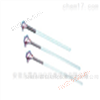
The DL-SYC21 tuning fork level switch is a new type of level switch. The instrument consists of a transmitting fork and an amplifier section, with two sets of piezoelectric crystals pressed at the base of the fork. One set serves as a driver to drive the fork to produce vibration, while the other set serves as a detector to convert the fork into a voltage signal. When the fork is obstructed, the amplitude of the vibrator decreases, the vibration frequency changes, and the relay outputs a switch signal. Thus achieving level limit measurement. The sensor material is 316 stainless steel, which can resist mild corrosion and is used for limit controllers and high/low level alarms.
Product Details

☆Product Introduction:
SYC21 tuning fork level switch is a new type of level switch. The instrument consists of a transmitting fork and an amplifier section, with two sets of piezoelectric crystals pressed at the base of the fork. One set serves as a driver to drive the fork to produce vibration, while the other set serves as a detector to convert the fork into a voltage signal. When the fork is obstructed, the amplitude of the vibrator decreases, the vibration frequency changes, and the relay outputs a switch signal. Thus achieving level limit measurement. The sensor material is 316 stainless steel, which can resist mild corrosion and is used for limit controllers and high/low level alarms.
☆ Working principle:DL-SYC21 tuning fork switch
The working principle of SYC21 type tuning fork level switch is based on whether the material has resistance to the vibrating tuning fork, detecting whether the material level has reached or exceeded a certain height, and issuing an on/off signal. The tuning fork of the sensor vibrates at its natural frequency. When the tuning fork touches liquid or other materials, its natural vibration frequency decreases, and energy is consumed in the friction between material particles, forcing the amplitude to rapidly decay and stop vibrating. The change in frequency activates the liquid level switch, generating an on/off signal.
☆ Typical applications:DL-SYC21 tuning fork switch
★ Tap water, mineral water ★ Pulp, glue, dye ★ Wastewater, mud, acid-base solutions ★ Liquids that can produce gases
★ Beer, beer fermentation agents, beverages ★ Dangerous places such as diesel ★ Solid powders with good fluidity
1、 Unboxing
Carefully open the packaging box and remove the filling inside. Carefully check each item on the packing list, including instrument model, installation accessories, instructions, etc. If you find any shortage, inconsistency with the packing list, or damage, please contact our company immediately.
2、 View the instruction manualDL-SYC21 tuning fork switch
This manual includes the technical parameters, installation and commissioning specifications of the instrument. Please carefully read each item in the manual. If you have any questions about the content in the manual, you can contact our company by fax or fax.
3、 Technical parametersDL-SYC21 tuning fork switch
★ Power supply: 24VDC (standard); 220VAC (optional) ★ Environmental temperature: -20 ℃~70 ℃
★ Output mode: SPDT relay (single pole double throw) ★ Medium temperature: -40 ℃~150 ℃
★ Working pressure: less than 2MPa ★ Medium density: as low as 0.6g/cm3
★ Delay: 1-60s (optional) ★ High and low level alarm: can be set to high or low level alarm on site
★ Power consumption: 0.5W ★ Explosion proof grade: Exd Ⅱ CT4
★ Electrical interface: M20 * 1.5 ★ Shell protection: IP66
★ Process connection: NPT 1 "thread installation (standard thread), flange installation (optional)
4、 Product Features
★ Strong adaptability:
The different electrical parameters and densities of the tested liquid do not affect the measurement. Scaling, agitation, turbulence, bubbles, vibration, moderate viscosity, high temperature, high pressure and other harsh conditions have no effect on the detection.
★ No need for calibration:
Due to the fact that the detection of tuning fork limit switches is not affected by the electrical parameters and density of the measured medium, no on-site calibration is required for any type of liquid being measured.
★ Maintenance free:
Due to the fact that the detection process of the tuning fork limit switch is completed by electronic circuits and there are no moving parts, maintenance is not required once it is installed and put into operation.
5、 Installation instructions
The tuning fork limit switch is usually installed on the side of the compartment wall to detect the upper and lower limit positions of the material level on the compartment wall; When it is inconvenient to open holes on the side of the warehouse, top mounting (installed at the top of the warehouse) can be used for installation, and the position should be selected to avoid material impact during feeding; It can also be installed on the pipeline to prevent the pump from running out of material.

★Attention:
When installing the sensor, insert it into the tank and use a wrench to tighten the hexagonal shape on the upper part of the sensor thread. Be careful not to manually twist the housing, as it may cause rotation between the housing and the probe rod during the tightening process. When leaving the factory, the connecting cables between the electronic unit and the sensor inside the shell have been connected. Forcefully twisting the shell will cause the internal connecting cables to break.
a.During installation and construction, be careful not to subject the fork to strong impact to avoid damaging the piezoelectric crystal.
b.Instrument sensors should avoid the impact of materials as much as possible. When installed horizontally, the two parallel fork plates of the fork body should be perpendicular to the ground (at this time, the fork body direction mark should be raised or lowered) to ensure that materials can easily flow out between the fork plates.
6、 Product debugging
(1) Check the power wiring:
All power wiring is connected to the terminal board at the top of the electronic unit.
(2) High and low level alarm selection:
The high and low position alarms can be set on site by selecting jump blocks from the high and low position alarms installed on the electronic unit. On the right side, it is a high-level alarm, and on the left side, it is a low-level alarm (usually set as a high-level alarm at the factory, but the output wiring can also be changed).
High level alarm: When the material submerges the center end of the sensor (or when the instrument malfunctions), a high level alarm signal is issued (the jumping block position is shown in Figure 1).
Low level alarm: When the material is below the center end of the sensor (or when the instrument malfunctions), a low level alarm signal is issued (the jumping block position is shown in Figure 2).

(3) Relay wiring
Each instrument is equipped with a set of single pole double throw relay contacts (SPDT). The relay serves only as a switch and cannot directly drive the alarm or other high-power equipment to operate. All control signals are output from the terminal block at the top of the electronic unit. When the green light is on, it indicates that the relay is working normally (no alarm, as shown in Figure 3). When the light is off, the relay is in an alarm state (when power is cut off or the instrument malfunctions, the relay is also in an alarm state, as shown in Figure 4).

Open the upper cover of the casing, which contains wiring terminals, toggle switches, light-emitting diodes (LEDs), and sensitivity adjustment buttons. Rotate the sensitivity adjustment knob clockwise to reduce sensitivity; Rotate counterclockwise to increase sensitivity. Usually, it is marked before leaving the factory and does not require calibration. For high viscosity liquid media, the sensitivity is generally reduced.
7、 Testing
When leaving the factory, the alarm is usually set to a high position. Connect the tuning fork type level switch to the power supply, and when the light is on, lift it up and insert it vertically into the water. The insertion depth should be greater than 25mm. At this time, the output indicator light will turn off; Lift the tuning fork away from the water surface again, and the output indicator light will turn on, indicating that the instrument is working properly.