- Phone
-
Address
253 Yulu Road, Jiading District, Shanghai
Product Categories
Ankerui Electric Co., Ltd


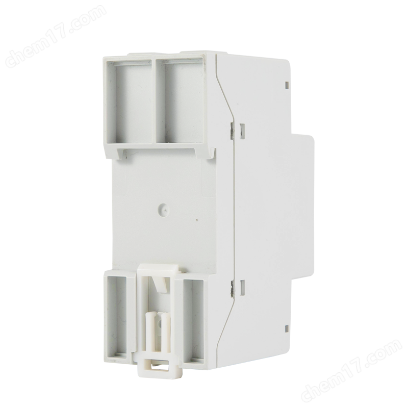
Ankerui single-phase electric meter bidirectional metering RS485 communication rail type
NegotiableUpdate on 05/18
- Model
- Nature of the Manufacturer
- Producers
- Product Category
- Place of Origin
Overview
ADL200 single-phase electronic energy meter is mainly used to measure single-phase active energy in low-voltage networks, and can also measure voltage, current, power and other electrical quantities
Product Details
The ADL200 single-phase electronic energy meter is mainly used to measure single-phase active energy in low-voltage networks, and can also measure voltage, current, power, and other electrical quantities,It can also be equipped with RS485 communication function, making it convenient for users to monitor, collect and manage electricity usage. It can be flexibly installed inside the distribution box to achieve different areas and requirementsMeasurement, statistics, and analysis of sub items of electrical energy under the same load. The product complies with national standardsaccurate
Auxiliary power failureFault manifestationThe instrument flashes or does not light up after being powered on.troubleshooting1. Check whether the wiring of the auxiliary power supply is consistent with the wiring diagram of the instrument, and whether there is any looseness or detachment in the wiring;2. Use a multimeter to measure whether the input voltage of the auxiliary power supply is within the normal operating voltage range of the instrument.6.2 Signal input faultFault manifestationThe instrument displays inaccurate power or energy counting after being powered on.troubleshootingSwitch the instrument display interface to the power (active power P, power factor λ) interface, and check if the power display is negative and the power factorIs it between 0.9-0.95? Then check if the input and output of the current signal line are reversed (i.e. the input line of the current must be connected to the instrument)The incoming end should be consistent with the wiring diagram on the instrument.6.3 Communication FailureFault manifestationThe instrument cannot communicate normally with the upper computer after being powered on.troubleshootingThe voltage value between communication outputs A and B of the measuring instrument should be between+(4.4-4.5) V;2. Check if the communication wiring method is correctly connected according to the wiring diagram requirements (i.e. the communication wiring terminals A/B of the instrument should be connected to the communication serial port)Corresponding to A/B


Similar Product Recommend


