-
E-mail
sale_xaspzy@sina.com
-
Phone
13484951492
-
Address
13th Floor, Unit 1, Building 3, Gaoke Shangdu Mocha, Zhangba 5th Road, High tech Zone, Xi'an City, Shaanxi Province
Product Categories
Xi'an Saipu Automation Instrument Technology Co., Ltd

Analysis of CO and O2 composition at the outlet of flue gas furnace
NegotiableUpdate on 11/24
- Model
- Nature of the Manufacturer
- Producers
- Product Category
- Place of Origin
Overview
Analysis of CO and O2 composition at the outlet of the flue gas furnace ..
Product Details
Online gas analysis system
------Outlet of flue gas generator
Xi'anSaipu Automation Instrument Technology Co., Ltd
The analyzer system provided by the bidder, including design, production, installation, and related technical documents, shall comply with the following standards and specifications:------Outlet of flue gas generator
Xi'anSaipu Automation Instrument Technology Co., Ltd
GB 50093 Code for Construction Acceptance of Automation Instrumentation Engineering
HG/T 20636~20639 Design Regulations for Chemical Automation and Automation Engineering
Functional identification and graphic symbols of HG-20505 process measurement and control instruments
Design and Installation of EEMUA NO.138 Online Analyzer
ASME. ANSI B1.20.1 NPT taper pipe thread, universal type
ASME/ANSI B16.5 pipe flanges and flange fittings
API RP550 Instrument Installation Manual
ISA S50.1 Industrial Instrument Analog Signal
IEC 60079-1998, GB3886 Explosion proof electrical equipment for explosive environments
IEC 529, GB4208-2000 Instrument Protection
MSS-SP-25 nameplate and imprint
ANSI/NEMA ICS6 Industrial Control Equipment and System Enclosures
SH3006-1999 Design Specification for Petrochemical Control Room and Automatic Analyzer Room
SH3005-1999 Design Specification for Selection of Automation Instruments in Petrochemical Industry
GB3836.01~12-91 Explosion proof Electrical Equipment for Explosive Environments
GB 50058-92 Code for Design of Electrical Installations in Explosive and Fire Hazardous Environments
NFPA No.70 National Electrical Code
NFPA No.496 Cleaning of Electrical Equipment Enclosures
ISA PR 12.1 Electric Instruments in Hazardous Environments
ISA S 12.4 Instrument Blowout for Reducing Hazardous Area Levels
IEC 79 Electrical equipment for use in explosive gas environments
HG/T 20636-20639-1998 Design Regulations for Chemical Plant Automation Engineering
Design and Installation of EEMUA No.138 Online Analyzer System
HG-20505-2000 Text codes and graphic symbols for process detection and control systems
HG/T 20516-2000 Design Specification for Automatic Analyzer Room
HG/T 20512-2000 Design Specification for Instrument Piping and Wiring
HG/T 20513-2000 Design Specification for Instrument System Grounding
PGB50093-2002 Code for Construction and Acceptance of Industrial Automation Instrumentation Engineering
Equipment manufacturing and ordering reference standards
HG/T 20502-2000 Text codes and graphic symbols for process detection and control systems
HG/T 20516-2000 Design Specification for Automatic Analyzer Room
HG/T 20512-2000 Design Specification for Instrument Piping and Wiring
HG/T 20513-2000 Design Specification for Instrument System Grounding
HG/T 20511-2000 Design Regulations for Instrument Alarm and Safety Interlocking System
GBJ93-86 Code for Construction and Acceptance of Industrial Automation Instrumentation Engineering
1Equipment Overview
The SP8000 online analysis device provided by Party B adopts the direct extraction method and achieves continuous online monitoring of oxygen and CO content at the outlet of the flue gas generator through advanced and reliable sampling, pretreatment, and detection technologies.
1. Performance and technical characteristics
a)System Control
The gas sampling and pretreatment system is automatically controlled by a Siemens programmable logic controller (PLC) to achieve continuous automatic operation of gas sampling measurement, probe automatic blowback maintenance, and condensate automatic discharge. If manual blowback or drainage is required in the measurement state, simply trigger the corresponding operation key to automatically complete and enter the measurement state. When the operation button is not triggered, the system operates in automatic mode, automatically measuring, timing blowback, timing drainage, timing analysis instrument zero point, and span calibration.
The gas sampling and pretreatment system has powerful protection measures such as probe blowback pressure detection alarm, condensation and water removal detection alarm, and flow detection alarm entering the analytical instrument. It has strong system automatic fault handling ability and self-protection ability. The system is always in a self diagnostic state during continuous operation, making it a truly unmanned environmental monitoring device.
b)Sampling and preprocessing device
i.Sampling probe
The sampling probe is manufactured by ABB component integration, and the filter is a high-precision double-layer composite structure gas sampling probe. The sampling probe includes: probe tube, heater, FE filter unit, installation flange, protective box and other components. The heating temperature can be adjusted to keep the filter dry under harsh sampling conditions (high moisture content)
The main technical specifications of the sampling probe are:
Filtering accuracy: 0.1-0.3 μ m
Filtration capacity: ≤ 2000g/Nm3
Filtration efficiency: ≥ 99.6%
Suitable temperature: ≤ 750 ℃
ii.Automatic blowing device for sampling probe
The sampling probe adopts the internationally advanced internal and external pulse vibration blowing technology for blowing. The sampling probe is equipped with a compressed air storage tank, a compressed air fine filter, a compressed air distribution unit, and a pressure alarm device. Its instantaneous blowing technology ensures sufficient pressure and flow during blowback, and with the unique filtering method of a high-precision filter, thoroughly removes dust attached to the surface of the filter, resulting in good blowback effect.
iii.Sampling pipeline
External users of the sampling pipeline can adopt a constant temperature heat tracing method. The self constant temperature heat tracing tube heats uniformly, stably, and quickly without the need for external temperature control devices. The heating temperature can reach up to 160 ℃, effectively avoiding sample gas condensation and pipeline blockage; Simultaneously avoiding corrosion and measurement errors caused by sulfide dissolution. The sampling pipeline adopts polytetrafluoroethylene (Teflon) pipe, which has stable performance, corrosion resistance, and high temperature resistance. Long term use does not require replacement.
iv.Sampling pre-processing device
The sampling preprocessing device mainly includes: sample gas condenser, peristaltic drainage pump, sampling solenoid valve, programmable controller, etc. The components such as the suction pump and solenoid valve are explosion-proof to ensure the normal and safe operation of the system in an explosion-proof environment. Under the automatic action of sampling probes, vacuum pumps, condensers, etc., the tested gas completely removes dust, moisture, tar, etc. from the flue gas without changing the composition and concentration of the gas to be tested during the process. The system is equipped with a high-precision filter and humidity alarm, with a filtration accuracy of 0.1 μ m. In the event of a system accident (sudden increase in moisture in the process pipeline or condenser failure), the system will automatically stop the operation of the vacuum pump, automatically close the sampling gas path, and output an alarm signal to prevent moisture and other impurities from entering the analysis system, effectively protecting the analysis instrument.
Preprocessing technology: The preprocessing technology used in this explosion-proof gas online continuous monitoring system is a targeted and systematic design for on-site application conditions and process gas sample conditions. The correct matching and reasonable combination achieved enable the analytical instruments and preprocessing devices to adapt well to the process gas sample conditions, ensuring long-term reliable and stable operation of the system.
c)Analysis instrument:
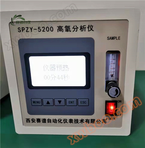
The principle of the magnetic oxygen analyzer produced by Xi'an Saipu Automation Instrument Technology Co., Ltd. is to use the physical property of the high magnetic susceptibility of oxygen in flue gas components to determine the oxygen content in flue gas. Oxygen is a paramagnetic gas (a gas that can be attracted by a magnetic field is called a paramagnetic gas), which is attracted in an uneven magnetic field and flows towards stronger magnetic fields. A heating wire is installed at this location to increase the temperature of oxygen and decrease its magnetic susceptibility, resulting in a decrease in magnetic field attraction. The magnetic field is then pushed out by unheated oxygen molecules with higher magnetic susceptibility, causing the phenomenon of "thermal magnetic convection" or "magnetic wind". At a certain gas sample pressure, temperature, and flow rate, the oxygen content in the gas sample can be measured by measuring the magnitude of the magnetic wind. Due to the fact that the thermistor (platinum wire) serves as both the two bridge arm resistors of the unbalanced bridge and the heating resistor wire, a temperature gradient occurs under the action of magnetic wind, that is, the temperature of the intake side bridge arm is lower than that of the exhaust side bridge arm. The unbalanced bridge will output corresponding voltage values depending on the oxygen content in the gas sample. Magnetic oxygen analysis adopts stable and reliable thermal magnetic gas sensing technology and microprocessor technology, with functions such as LCD display, upper and lower limit alarm, standard signal output, and relay contact alarm output. Suitable for continuous monitoring of oxygen purity in air separation oxygen production and other gas production processes. It can also be used for rapid analysis of oxygen concentration in the laboratory.
Instrument features:
·Adopting paramagnetic detection principle, high sensitivity and good stability
·Integrated structure, small size, light weight, easier installation and use
·Adopting a large LCD display screen and a fully Chinese operation menu
·Equipped with timed automatic storage function, the stored data can be viewed at any time
·Can set upper and lower limit alarm points, with alarm contact output
·The output current can be set to 0-10mA or 4-20mA
·Can be connected to a printer to achieve timed automatic printing
·Equipped with RS232 communication port, it can be connected to a computer to achieve real-time data transmission, data storage, curve trend chart, printing report and other functions
·Online calibration with available standard gas
Main technical indicators:
·Measurement range: 0-100% O2
·Accuracy: ± 1% O2
·Minimum division value: 0.01% O2
·Stability: ≤± 0.10% O2//24h
·Repeatability: ≤± 0.10% O2
·Response time: T90 < 40 seconds
·Output signal: fully isolated DC 0~10mA, 4~20mA
·Power supply: 220VAC ± 10% 50Hz ± 5%
The principle is to use the physical property of the high magnetic susceptibility of oxygen in the components of flue gas to determine the oxygen content in the flue gas. Oxygen is a paramagnetic gas (a gas that can be attracted by a magnetic field is called a paramagnetic gas), which is attracted in an uneven magnetic field and flows towards stronger magnetic fields. A heating wire is installed at this location to increase the temperature of oxygen and decrease its magnetic susceptibility, resulting in a decrease in magnetic field attraction. The magnetic field is then pushed out by unheated oxygen molecules with higher magnetic susceptibility, causing the phenomenon of "thermal magnetic convection" or "magnetic wind". At a certain gas sample pressure, temperature, and flow rate, the oxygen content in the gas sample can be measured by measuring the magnitude of the magnetic wind. Due to the fact that the thermistor (platinum wire) serves as both the two bridge arm resistors of the unbalanced bridge and the heating resistor wire, a temperature gradient occurs under the action of magnetic wind, that is, the temperature of the intake side bridge arm is lower than that of the exhaust side bridge arm. The unbalanced bridge will output corresponding voltage values depending on the oxygen content in the gas sample. Magnetic oxygen analysis adopts stable and reliable thermal magnetic gas sensing technology and microprocessor technology, with functions such as LCD display, upper and lower limit alarm, standard signal output, and relay contact alarm output. Suitable for continuous monitoring of oxygen purity in air separation oxygen production and other gas production processes. It can also be used for rapid analysis of oxygen concentration in the laboratory.
Instrument features:
·Adopting paramagnetic detection principle, high sensitivity and good stability
·Integrated structure, small size, light weight, easier installation and use
·Adopting a large LCD display screen and a fully Chinese operation menu
·Equipped with timed automatic storage function, the stored data can be viewed at any time
·Can set upper and lower limit alarm points, with alarm contact output
·The output current can be set to 0-10mA or 4-20mA
·Can be connected to a printer to achieve timed automatic printing
·Equipped with RS232 communication port, it can be connected to a computer to achieve real-time data transmission, data storage, curve trend chart, printing report and other functions
·Online calibration with available standard gas
Main technical indicators:
·Measurement range: 0-100% O2
·Accuracy: ± 1% O2
·Minimum division value: 0.01% O2
·Stability: ≤± 0.10% O2//24h
·Repeatability: ≤± 0.10% O2
·Response time: T90 < 40 seconds
·Output signal: fully isolated DC 0~10mA, 4~20mA
·Power supply: 220VAC ± 10% 50Hz ± 5%
Infrared gas analyzer can be used for continuous measurement of gas concentrations such as NOX, SO2, CO, CO2, CH4, etc., and can simultaneously measure one or more gas components. Infrared gas analyzer is a multi-channel, multi-component analyzer. The instrument adopts the world's advanced infrared gas detection technology, which has excellent stability, selectivity, and high sensitivity. It is widely used for continuous monitoring of flue gas emissions from fixed pollution sources in various industries such as power, metallurgy, building materials, and chemical engineering, as well as process control analysis
| Measuring principle |
Non dispersive infrared methods: NOX (NO or NO2), SO2, CO, CO2, CH4 Electrochemical method: O2 |
|||
| Measure components | NO, NO2, SO2, CO, CO2, CH4 can be measured, and any one or two components can be added to each component | |||
|
Measurement range Can be designed according to requirements |
Minimum range | maximum range | ||
| NO | 0~1000ppm | 0~20% | ||
| NO2 | 0~200ppm | 0~100% | ||
| SO2 | 0~200ppm | 0~100% | ||
| CO | 0~500ppm | 0~100% | ||
| CO2 | 0~200ppm | 0~100% | ||
| CH4 | 0~200ppm | 0~100% | ||
| repetitiveness | ≤±0.5%F.S. | |||
| zero drift | ≤±1%F.S./7d | |||
| Full-scale drift | ≤±1%F.S./7d | |||
| linearity | ≤±1%F.S | |||
| response time | T90 ≤ 20 seconds (at a sample gas flow rate of 0.5L/min) | |||
| output signal | Analog output: 4-20uA Maximum load: 750 Ω Digital communication RS485 (optional) | |||
| environmental conditions | 5 ℃~45 ℃, not exceeding 90% RH | |||
| power supply voltage | AC220V 50Hz | |||
| Overall dimensions | 440(W)×160(H)×400(D)mm | |||
|
Conditions of the measured gas |
temperature | 0~50℃ | ||
| traffic | 0.5L/min±0.2L/min | |||
| dust | Particles not exceeding 1 μ m, not exceeding 200 μ g/Nm3 | |||
| pressure | Not exceeding 10kPa (the outlet end of the tested gas should be at atmospheric pressure) | |||
| aerosol | none | |||
| 水分 | Not exceeding 5 ℃ saturation (no condensation) | |||
◆working principle
When the system is in sampling state, the measured gas enters the preprocessing device, passes through the filter by the switch valve, goes to the YZ pressure converter, passes through the flow meter by the switching valve, and enters the analysis instrument for analysis; Fast bypass discharge can reduce delay time. Blow back nitrogen through pressure reducing valves, filters, regulating valves, etc. Manual switching of valves can achieve gas path switching operations for sampling and calibration. Analyze exhaust emissions and bypass rapid discharge back into the process pipeline.
◆ Installation and wiring
The installation work of this system mainly includes the installation of sampling pipelines and analysis cabinets. The environmental conditions should meet the requirements of normal sampling and normal working conditions in the technical characteristics. Only by using this system in the designated environment can the safe operation and normal functioning of the system be guaranteed.
Installation of analysis cabinet
The analysis cabinet should be installed on the ground, and the mechanical vibration at the installation location should be negligible.
The large components (such as analytical instruments) inside the analysis cabinet are disassembled and packaged separately. When installing, refer to the system analysis flowchart, assembly diagram of the analysis cabinet, and electrical wiring diagram.
Installation of sampling pipeline
The sampling pipeline is connected using PFA tubing. The sampling pipeline should be evenly inclined to avoid bending, concave water accumulation, and other phenomena.
The exhaust pipe is connected with PFA pipe. Analyze the exhaust emissions back to the process pipeline, and ensure that the exhaust gas path is unobstructed, without throttling or any air resistance, in order to avoid reducing detection accuracy or affecting the normal operation of the system.
◆Sealing performance of the system:The airtightness inspection of the system shall be carried out in accordance with the enterprise standards.
◆Grounding:In order to ensure safe operation and avoid electromagnetic interference, the analysis cabinet is reliably grounded through the grounding terminal, with a grounding resistance of less than 4W.
◆ Wiring:Referring to the electrical wiring diagram, the wiring terminals inside the analysis cabinet electrical box need to be externally connected or interconnected during on-site installation, and all other electrical circuits should be connected before leaving the factory. Before the system is put into operation, the external electrical circuits should be connected correctly and the connections on each component should be checked for looseness or detachment.
2. Technical specifications
2.1 Basic System Parameters
Applicable sample gas temperature: ≤ 250 ℃
Dust content: ≤ 2000g/Nm3
Response time: T90 ≤ 15s
Backblowing gas source: nitrogen, 0.3-0.8MPa
Gas consumption: maximum: 1.2m3/h, Average: 1m3/h
Power consumption: 220/380V AC 50Hz; 5000VA/set
Note: The system response time and power consumption are calculated based on a sampling pipeline of 50 meters.
2.2 Analytical Instruments
oxygen analyzer
Measurement range: 0-25% (automatic range conversion)
Resolution: 0.01%
Oxygen accuracy: ≤± 0.01% oxygen (including noise, linearity, and repeatability)
Temperature drift: ≤± 1%
Stability: ≤± 1%
Zero drift: ≤± 0.1%
Reaction time: ≤ 1 second
Diffusion reaction time in still air: ≤ T63/T90
meet the standard
Electromagnetic compatibility IEC (EN) -61326 standard, electronic equipment for measurement, control, and laboratory use.
EN50104 standard, performance requirements and testing methods for oxygen electronic instruments.
EN50271 standard, electronic instruments for detecting flammable gases, toxic gases, and oxygen.
Infrared CO analyzer
Measurement range: 0-5%
Resolution: 0.01%
Temperature drift: ≤± 1%
Stability: ≤± 1%
Repeatability: ≤± 0.5% F.S
Zero drift: ≤± 1.0% F.S/7 days
Full range drift: ≤± 1.0% F.S/7 days
Linearity: ≤± 1% F.S
Reaction time: ≤ 1 second
Diffusion reaction time in still air: ≤ T63/T90
2、 Equipment detailssupplydetails
《SP800Type 0 gas onlineAnalysis Devicequantity1set
| Serial number | Name | Specification Model | manufacturer | quantity |
| Analysis instrument host |
oxygen analyzer (Magnetic oxygen type) |
O2:0-25% |
SIEMENS detector |
1 |
| Analysis instrument host | Infrared CO analyzer | CO:0-5% |
SIEMENS detector |
1 |
| Analysis cabinet | Analysis cabinet | 1800*600*600 | Xi'an Saipu | 1 |
| Preprocessing device | Sampling vacuum pump | LV-2 | UK CAP | 1 |
| pressure sensor | YX-100-T | Xiyi | 1 | |
| Automatic drain device | FT-80PY | Germany M&C | 1 | |
| gas condenser | 1-3°C | Germany Beile | 1 | |
| Precision air filter | FT-IQAD | Germany M&C | 1 | |
| Mist filter | DF-O23 | Germany M&C | 1 | |
| Peristaltic drainage pump | Williamson 0.1-1L/h | William of England | 1 | |
| Sampling device | Gas specific probe | Stainless steel anti-corrosion structure, internal and external cyclone structure | Xi'an Saipu | 1 |
| Electric Ball Valve | MXB1-15-E | Japanese CKD | 1 | |
| Sampling tube | Polytetrafluoroethylene ¢ 10 | Retek, USA | 20 | |
| Backblowing device | Electric Ball Valve | MXB1-15-E | Japanese CKD | 1 |
| Blowback tube | Polytetrafluoroethylene ¢ 10 | Retek, USA | 10 | |
| Backblowing explosion-proof box | BJX-11 | pfau | 1 | |
| Heat tracing device | Explosion proof temperature controller | DWL | bring peace to a country | 1 |
| Explosion proof electric heating belt | 20-180℃ | bring peace to a country | 30 | |
| control unit | PLC | S7-200 | SIEMENS | 1 |
| Electrical control unit | SIEMENS | 1 | ||
| On site sound and light alarm | On site sound and light alarm | S-S | Donggang | 1 |
| standard gas | standard gas | 4L | Shanghai Weichuang | 2 |
4.2 Spare Parts List
| serial number | Name and Specifications | quantity | Remarks |
| 1 | Special gas cylinder nut and sealing ring with a diameter of 6 | 2 sets | |
| 2 | Special anti blow tube nut, sealing ring with a diameter of 14 | 2 sets | |
| 3 | Special gas cylinder nut and sealing ring with a diameter of 3 | 2 sets | |
| 4 | Filter paper 4.9 type | 2 sets | |
| 5 | Poly (tetrafluoroethylene) pipe with a diameter of 7 and a diameter of 4 | 2 meters * 4 | |
| 6 | Poly (tetrafluoroethylene) pipe with a diameter of 2 and a diameter of 0.5 | 2 meters * 4 |
3.2 Implementation Schedule of Party B
After the contract is signed, organize and arrange the various tasks of the project according to the agreed time schedule between Party A and Party B. The second party shall be responsible for managing all implementation steps of the control system in accordance with the supply scope stipulated in the contract, including system design, production organization, equipment assembly, inspection and testing, packaging and transportation, guidance on installation and commissioning, system integration and commissioning, technical training, trial operation, acceptance and delivery, post sales services, etc. Designate an engineer with excellent technical and engineering capabilities and who has participated in similar project management multiple times as the project manager for this project, and designate several project engineers (including software engineers and hardware engineers) to be responsible for project design, service, and other work. We will inform Chongqing Iron and Steel of the project manager's name, mobile phone number, office phone number, mailing address, email address, etc. by fax. The project manager has similar experience in engineering project management. The project manager is responsible for comprehensive engineering management, business and technical matters, such as organizing system design, engineering schedule arrangement, manufacturing confirmation, programming and technical services, drawing documents, factory and on-site testing, document preparation, start-up, commissioning and on-site system testing, environmental protection bureau comparison, system acceptance and other work.3.3 Acceptance
1. Equipment acceptance standards and acceptance procedures(1) Final acceptance location: Designated location by Party A:
(2) Acceptance procedure: Within 3 days of the arrival of the goods, Party A shall open the box for acceptance according to the technical agreement attachment. If Party A does not raise any written objections within one week, it shall be deemed that the equipment has been accepted as qualified.
2. Installation, debugging, acceptance standards and acceptance procedures
(1) Final acceptance location: designated by Party A;
(2) Acceptance procedure: Within 3 days after the system installation and debugging are completed, Party A shall conduct acceptance inspection; The acceptance adopts the method of input standard gas inspection. If the error between the instrument measurement and the standard gas concentration value is within ± 1% FS, it is considered to be qualified for acceptance; System acceptance is qualified; The first party shall sign and take effect on the "On site Service Confirmation Form"; If Party A fails to sign and raise any written doubts within one week after the system installation and debugging are completed, it shall be deemed that the system acceptance is qualified.
3.4 On site technical services
During the unboxing inspection, installation, start-up and commissioning of all equipment and systems, Party B shall dispatch experts stationed at the construction site to provide on-site engineering technical services.The dispatched professionals are responsible for system installation guidance, power on testing, debugging, on-site training, engineering acceptance, and other related work. Dispatch on-site debugging personnel to comply with national laws and regulations during debugging and training, and abide by relevant regulations on site during on-site work. The transportation, living, and other expenses required for the experts stationed on site shall be borne by Party B, while Party A shall provide on-site services and office convenience.
3.5 Open box inspection
The first party confirms that the unpacked goods have arrived at the unpacking site, prepares the necessary space, tools, and manpower for unpacking, and prepares the storage location for the equipment after unpacking. Notify Party B of the specific unboxing time, location, and on-site preparation, and notify other relevant personnel (such as inspection personnel). Upon receiving notification from Party A, Party B shall dispatch personnel to the site within the specified time. Confirm the storage conditions and environment of on-site equipment. Both parties jointly inspect the external packaging of the equipment and confirm that it has not been opened. Both parties will open and inspect each box individually. Confirm the quantity and model of the equipment based on the packing list, inspect the appearance of the equipment, and record the results of the unpacking inspection.Both parties shall finally fill in the report on the unpacking acceptance results and sign it.
4、 Packaging, transportation, and storage
(1) Requirements for packaging and transportation
Responsible for the packaging and transportation of the system. If any equipment damage occurs during the packaging and transportation process, the manufacturer shall bear full responsibility.
1. Purpose
To avoid damage caused by equipment during transportation and storage, and ensure the safety of the equipment before installation.
2. Packaging method
Based on the characteristics of the goods and the packaging and transportation features of the industry. Choose wooden box packaging type and ensure that the goods are intact and easy to ship during transportation and storage.
Closed packaging: A form of packaging equipment in a closed wooden box made of wooden boards, suitable for equipment with moisture-proof, anti-corrosion requirements or high precision and value.
3. Packaging label: Clear, conspicuous, standardized, specific format and content shall be provided to Xi'an Daojing Instrument Co., Ltd. based on the premise of the owner's shipment.
4. Transportation
During the storage and transportation of goods or equipment, wooden crate packaging should be chosen to prevent damage or injury.
For equipment, its packaging is sturdy and has the function of preventing compression and collision.
The equipment is transported by car to the user's designated destination, and its packaging takes into account shock resistance.
The packaging label is obvious, the handwriting is clear and easy to distinguish, and it can be stored in sunlight for 6 months without fading.
(2) Storage requirements
The manufacturer shall submit storage system requirements in writing to prevent any damage to the system.
1. After the equipment arrives at the site, try to store it in the warehouse as much as possible before opening the box; If the equipment in the warehouse needs to be stored outdoors, it is necessary to pay attention to rain protection.
2. After unpacking the equipment, it must be stored in the warehouse and it is recommended not to place it outdoors easily.
3. Please do not invert the equipment marked on the packaging box.
4. Devices marked with "Handle with Care" on the packaging should not be bumped during storage and transportation.
5. After unpacking, the equipment should be marked with moisture-proof labels, and moisture-proof measures should be taken during storage.
For technical proposal information requests, please call: