-
E-mail
wjb@cykeyi.com
-
Phone
13837189935
-
Address
201, 2nd Floor, Building 5, Zhengzhou Yida Technology New City, Jinzhan Street, High tech Zone, Zhengzhou City
Zhengzhou Chengyue Scientific Instrument Co., Ltd
Design scheme of powder coated magnetron coating instrument
Date: 2025-08-14Read: 2
The following is a detailed design plan for powder coated magnetron coating equipment, covering equipment architecture, key modules, process control, and innovative points, suitable for functional coating of metal, ceramic, and polymer powders (such as conductivity, wear resistance, corrosion resistance, etc.):
1. Overall design objective
Applicable powder: particle size1μm-500μm(Can be extended to the nanometer level)
Coating type: Metal(Al, Cu)Oxide(Al₂O₃, TiO₂)Nitrides(TiN, CrN)
Core indicators:
Uniformity of film thickness:±5%(Particle size>10μmWhen)
Coverage rate:>95%(No exposed areas)
Capacity:0.5-5 kg/h(Depending on powder density)
2. Design of equipment core module
(1)Powder Movement System
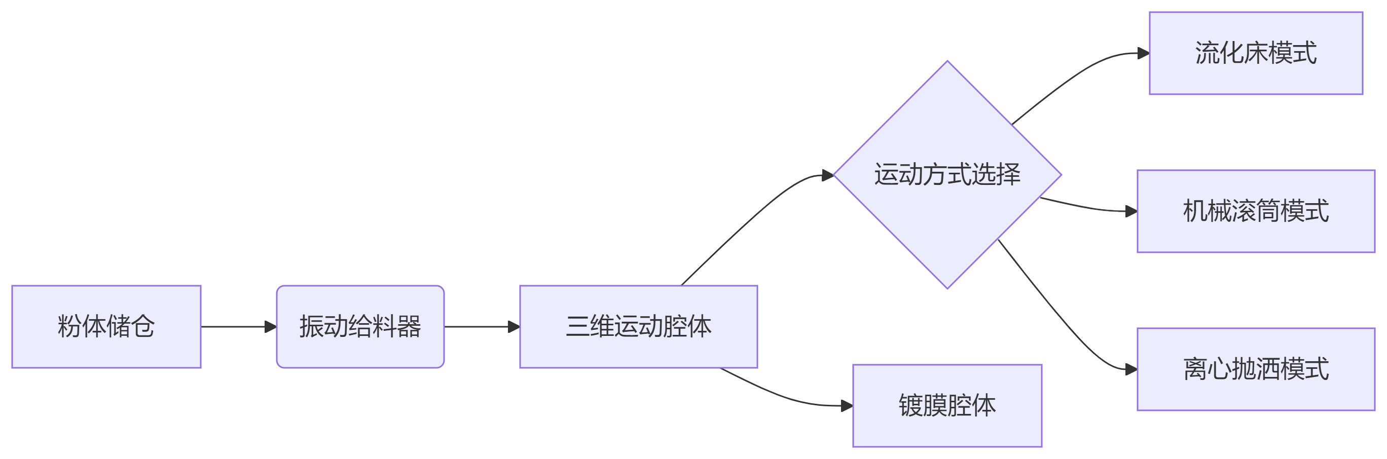
Fluidized bed mode:
Gas flow rate:0.1-1 m/s(Adjust according to powder density)
Distribution plate aperture: powder particle size5-10times
Applicable scenarios: Lightweight powders (such asSiO₂,Polymer microspheres)
Mechanical drum mode:
Speed:5-30 rpm(Tilt angle)10-15°)
Built in baffle: enhances powder rolling and avoids“avalanche effect”
Applicable scenarios: high-density powders (such asWC-Co,Metal powder)
(2)Magnetron Sputtering System
component |
Parameter requirements |
Innovative Design |
Target material layout |
4-6Symmetrical arrangement of targets (target base distance)80-150mm) |
Rotatable target holder(±30°Swinging) |
Magnetic field configuration |
Closed magnetic field strength>800Gauss |
Electromagnetic coil dynamically adjusts plasma density |
Power system |
pulseDC(Frequency)50-100kHz) |
Cleaning powder surface in anti sputtering mode |
(3)auxiliary system
Plasma pretreatment:
RFSource(13.56MHz, 100-300W)Remove organic matter from the surface of the powder
Ar/O₂Mixed gas (proportion)4:1)Activated surface
Online monitoring:
Laser particle size analyzer (real-time detection of powder dispersion)
Mass spectrometer (monitoring reaction gas partial pressure)
3. Key process control strategy
(1)Uniformity guarantee technology
Multi level motion coupling:
python
copy
download
#Example: Fluidized bed+Mechanical vibration composite program
def motion_control():
if particle_size < 50μm:
activate_fluidization(velocity=0.5m/s)
else:
activate_roller(angle=12°, rpm=15)
apply_vibration(freq=100Hz, amplitude=2mm)
Dynamic bias technology:
Apply to the powder-50Vto-200VPulse bias voltage (duty cycle)20-50%)
Attract ions to improve edge coverage (especially for>50μmPowder)
(2)Film quality control
parameter |
scope of control |
influence mechanism |
Working pressure |
0.3-1.0 Pa |
Too high leads to looseness, too low leads to slow speed |
Sputtering power density |
3-10 W/cm² |
Determine sedimentation rate and membrane density |
Powder temperature |
<80℃(Polymer based) |
Prevent thermal deformation or agglomeration |
4. Innovative design highlights
(1)Partition coating technology
Principle: The chamber is divided into a pre-treatment zone, a main coating zone, and a post-treatment zone, and the powder is continuously conveyed through a spiral conveyor
Advantage: Achieve single loading and complete cleaning-coating-Passivation of the entire process
(2)Intelligent feedback system
Sensor network:
Infrared thermal imager monitors the temperature field of powder
Plasma emission spectroscopy(OES)Real time analysis of membrane composition
AIRegulation:
based onLSTMModel predicts optimal power-Air pressure combination
Dynamically adjust the power distribution of target materials (such as increasing the power of edge targets)20%)
(3)Anti reunion solution
Static dispersion module:
exert5-10kVHigh voltage pulse (pulse width)1μs)
Make the powder carry the same charge and repel each other
Acoustic assistance:
40kHzUltrasonic crushing of soft aggregates
5. Typical application cases
(1)Lithium battery positive electrode material coating
Powder:LiNi₀.₈Co₀.₁Mn₀.₁O₂(Particle size)10-20μm)
Coating:5nm Al₂O₃
workmanship
Fluidized bed mode(ArGas velocity0.3m/s)
pulseDCSputtering (average power)2kW)
Substrate bias voltage-100V
effect:
Cycle life improvement>50%(4.5VCut off voltage
coatingCV<3%
(2)Wear resistant ceramic powder
Powder:Al₂O₃(Particle size)50-100μm)
Coating:TiN(Thickness)200nm)
workmanship
Drum mode (speed)20rpm)
Reactive sputtering(N₂/Ar=1:4)
Substrate heating150℃
effect:
Powder hardness from15GPa→18GPa
Decreased friction coefficient40%
6. Economic and safety design
project |
plan |
Target utilization rate |
Rotating target design (utilization rate>75%) |
Dust explosion prevention |
Nitrogen automatic fire extinguishing system+Oxygen content monitoring (<)8%) |
Maintain convenience |
Quick release chamber design (replacement of target material <10Minutes) |
7. Future expansion direction
Nano powder coating:
Develop an electric suspension device (replacing mechanical motion) suitable for<1μmpowder
Multi component gradient coating:
Realize composition gradient through multi-target co sputtering (such asAl→Al₂O₃)
Volume to volume integration:
Connect with powder granulation equipment to achieve coating-Integrated molding
Conclusion
This design scheme combines multidimensional motion control with innovative plasma engineering to solve the problem of uniformity in powder coating. The equipment is particularly suitable for the preparation of functional powders in fields such as new energy and aerospace, and its modular design allows for flexible adjustment of processes based on powder characteristics. In the next step, we need to focus on breaking through the problems of anti agglomeration and industrial mass production stability of nano powders.