-
E-mail
info@auniontech.com
-
Phone
15601689581
-
Address
3rd Floor, Building 6, No. 2007 Hongmei Road, Xuhui District, Shanghai
Shanghai Haoliang Optoelectronic Equipment Co., Ltd
Introduction to Machine Vision 3D Imaging Technology (II)
Date: 2025-12-02Read: 0
Introduction to Machine Vision 3D Imaging Technology (II)
structured light
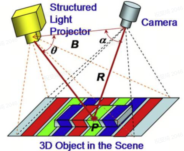
Structured light, using a laser diode (LD) or digital light processor (DLP), projects pre designed patterns with special structures (such as discrete light spots, stripe light, encoded structured light, etc.) onto the object being measured. Another camera is used to observe the deformation of the patterns reflected back from different height positions of the object. If the surface of the object being measured is a plane, the observed structured light pattern is similar to the projection, without deformation, but with a certain scale change based on distance. However, if the surface of the measured object is uneven and has height differences, the observed structured light pattern will undergo varying degrees of deformation with the height of the measured object. Based on these deformations, the position and depth information of the measured object can be calculated.
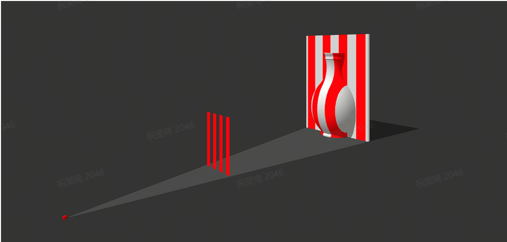
Structured light imaging generally consists of three steps (taking stripe projection technology as an example):
第1Step by step, stripe generation:Generate sine stripes through computer programming, project the sine stripes onto the object through a projection device, capture the bending degree of the stripes modulated by the object using a CCD camera, demodulate the bending stripes to obtain the phase, and then convert the phase into the height of the entire field. The four step phase-shifting method is used here, resulting in four fringes with a phase difference of pi/2. Then project the four stripes onto the measured object (mask) in a time-division manner, and collect the image on the left side of the figure below (of course, it is also four stripes). At the same time, four reference surface stripes (unmodulated, also four stripes) need to be collected.
Step 2, Phase Recovery:The modulated phase is calculated from the four modulated fringe patterns collected. The phase map obtained here is a truncated phase map because the result obtained by the four step phase shifting algorithm is calculated by the inverse tangent function, and is therefore limited to [- pi, pi], which means that whenever its value exceeds this range, it will start again.
Step 3, 3D reconstruction:The phase difference is obtained by subtracting the above two, which represents the height information of the measured object relative to the reference plane. Then, the phase and height conversion formula (where the corresponding parameters are calibrated) is used to obtain the image of the 3D structure. The specific 3D reconstruction relies heavily on the support of algorithms, and the algorithms required for the specific reconstruction process are also very complex.
Structured light 3D imaging technology is currently the main way for robots to perceive 3D vision. The structured light imaging system consists of several projectors and cameras, and commonly used structural forms include: single projector single camera, single projector dual camera, single projector multi camera, single camera dual projector, and single camera multi projector.
Structured light and binocular stereo vision are both based on the principle of triangulation, requiring a certain distance between the camera and projector or between two cameras in binocular vision, and a certain angle a (generally>15 °) to achieve measurement. Both have the disadvantage of large volume and easy obstruction if the surface of the measured object is steep or has steps.
A robot 3D vision guidance system developed based on structured light and 3D object recognition technology can achieve full freedom positioning and grasping of scattered and stacked parts within a large depth measurement range. Compared with traditional two-dimensional visual positioning methods, which can only recognize fixed depth parts and obtain partial degrees of freedom position information of the parts, it has higher application flexibility and a larger detection range. It can provide effective automation solutions for industrial problems such as machine tool loading and unloading, part sorting, and stacking.
Structured light technology has some similarities with laser triangulation, but the system is more complex and can obtain richer information, generating more detailed point clouds. Structured light cameras are more suitable for scenes where the object being measured is stationary, while laser triangulation cameras are more suitable for situations where the object is in motion, especially on conveyor belts or transmission lines. In scenes with complex ambient light or direct sunlight, high-power laser triangulation cameras have more advantages. The laser projects a very narrow wavelength of light, and the image sensor can filter out ambient light interference through a narrowband filter. Most structured light cameras use LED light sources, which pose no safety risks. Laser triangulation cameras use lasers, which pose potential safety risks to the eyes. For sub micron application scenarios, structured light cameras have more advantages, while laser triangulation cameras cannot achieve sub micron accuracy due to the presence of laser speckle. Structured light cameras can complete 3D imaging with a full field of view at once, unlike laser triangulation cameras that can only obtain depth information of the measured object's cross-section at once. In practical applications, structured light cameras project precisely calibrated white or blue light with special structures onto the object being measured. Common structures include parallel lines, stripes, or grids. When structured light is irradiated on the surface of the object being measured, the structure of the light will change with the height and curvature of the surface of the object being measured. Taking stripe shaped structured light as an example, the stripes will become thicker or thinner on the surface of the object being measured, which means that the sampling points in these areas are correspondingly closer or farther away from the camera. Specially designed pattern recognition and 3D reconstruction algorithms will complete 3D imaging based on the information. Some projectors of structured light cameras also have the function of RGB cameras to obtain texture and color information of the measured object.
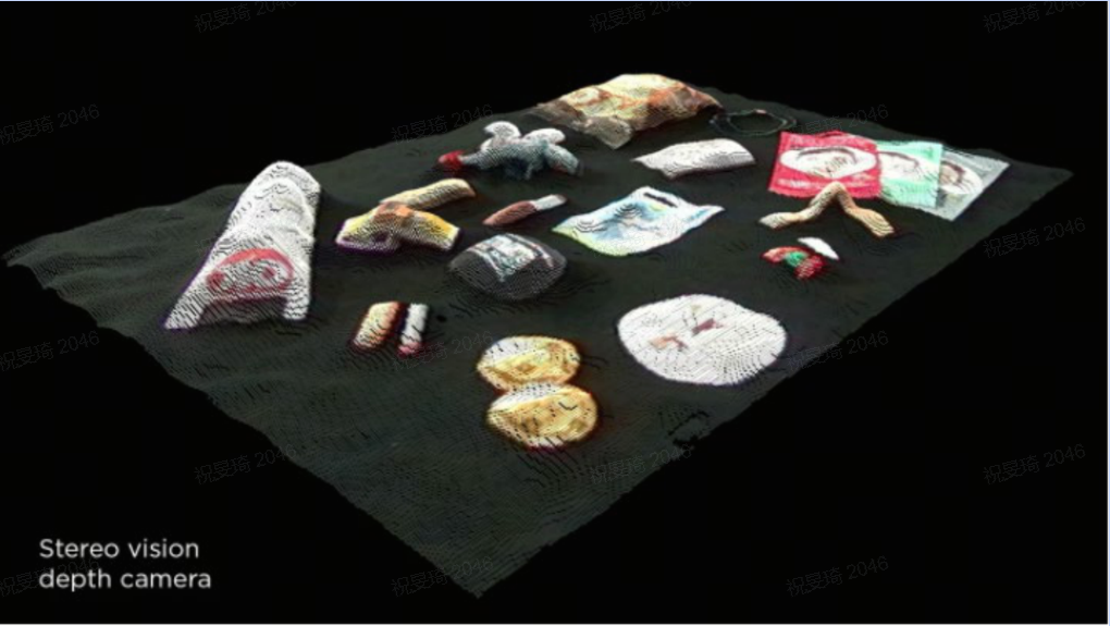
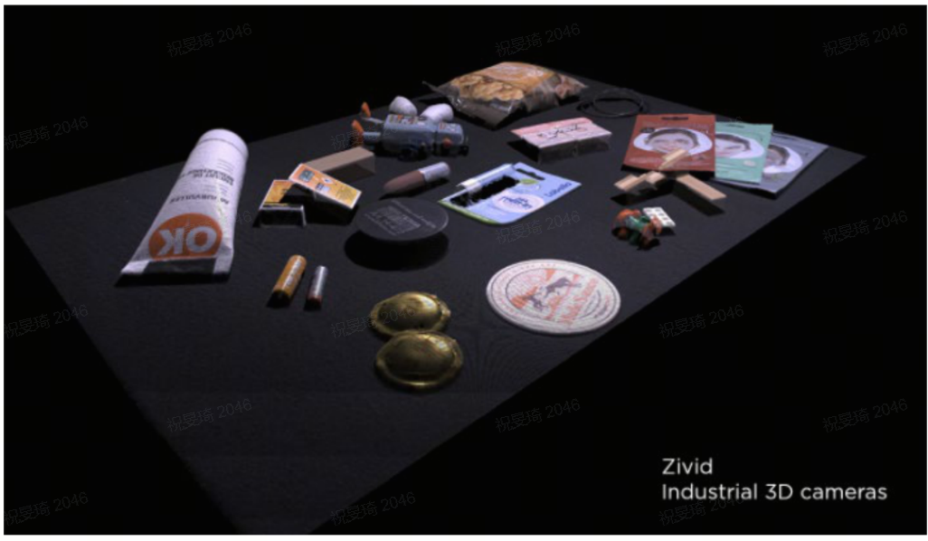
The ZIVID structured light camera of Haoai Intelligent Agent adopts a design of single projector and single camera, which is similar to active binocular stereo vision, but lacks one camera. By actively projecting structured light sources, easily recognizable feature points are artificially added to the target measurement object. Due to the pre known and non random structure, the computational complexity of feature extraction is lower, while also avoiding the problem of correlation calculation. The structured light camera with a single projector and camera, like active binocular stereo vision cameras, also faces issues of block averaging, resolution, and accuracy. The ZIVID structured light camera overcomes these issues by introducing structured light with both time-domain and spatial domain encoding. However, structured light cameras, like laser triangulation cameras, still experience data loss and detection errors for objects with mirror surfaces, dark colors, or high absorption rates. The following is a comparison of point clouds obtained by ZIVID structured light camera and binocular stereo vision camera:
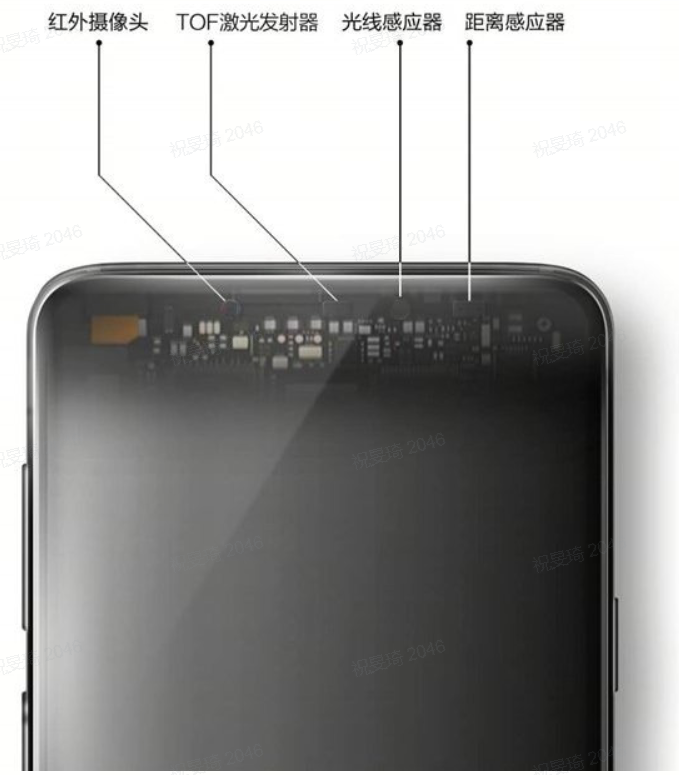
Xiaomi on Xiaomi 8 Transparent Exploration EditionsendAfter adopting the 3D structured light technology of the Android camp, OPPO subsequently used 3D structured light in the Find X, VivosendToF 3D super sensing technology with 300000 infrared measurement points. The effective depth information of ToF is 10 times that of structured light. In addition to higher information content, the working distance of ToF is also higher than that of structured light, with a usage distance of up to 3 meters, which is three times that of the latter.
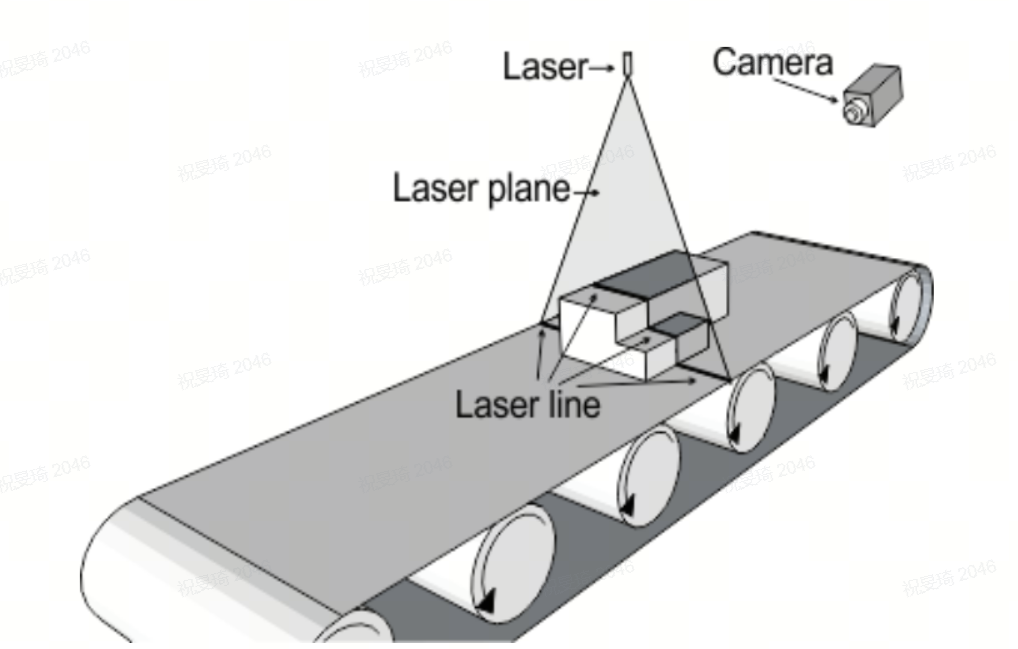
Laser triangulation
The laser triangulation measurement method is to form a certain angle between the camera lens and the laser, project the laser light source onto the surface of the object being measured, and generate the contour lines of the object's surface. To obtain a three-dimensional image of the object being measured, the object and the camera must undergo relative motion to generate multiple object surface contour lines. Finally, the camera combines these contour lines into a three-dimensional image. This method measures the geometric offset of a line, whose value is related to the height of the object. It is a one-dimensional imaging technology based on object scanning. According to the distance between the laser emitter and the object being measured, the laser point will appear at different positions in the camera's field of view. The triangular optical path is formed by laser points, cameras, and laser emitters, hence this technique is often referred to as triangulation. This technology is sensitive to structured or complex surfaces, and when the object being measured is too high, some laser lines may not reflect back to the camera due to obstruction.
According to the angle relationship between the incident beam and the normal of the measured object surface, laser triangulation can be divided into two types: oblique and direct. Direct type is when the angle between the incident beam and the normal of the measured object surface is 0. The oblique angle is when the angle between the incident beam and the normal to the surface of the object being measured is a>0. The common direct and oblique layout methods are shown in the following figure:
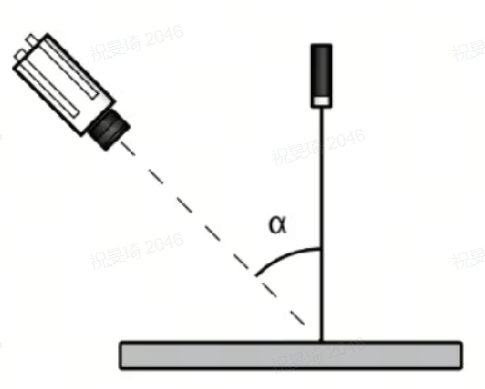
Direct type

Oblique shooting style
The principle of laser triangulation is introduced using the direct beam method as an example.

The red, green, and blue dashed lines in the above figure indicate that reflected light from different distances will be projected onto different positions on the camera imaging surface, and the distance between the sensor and the surface of the object being measured will be calculated based on these positions. The change in vertical distance d will result in a change in the camera's imaging position d. It can be seen that the measurement range and accuracy of this technology are mutually constrained. The higher the accuracy, the smaller the displacement changes reflected on the camera imaging plane due to changes in vertical distance. In this way, the range of changes in the target position is inevitably limited. As the depth of the target increases, it will soon exceed the physical size of the camera imaging sensor. In the specific design of optical systems, a balance needs to be made between measurement range and measurement accuracy based on measurement requirements to achieveExcellenteffect.
The camera based on laser triangulation mainly consists of a laser diode (LD), a converging lens, a receiving lens, an image sensor, and a signal processing unit. The specific optical path is shown in the following figure:

X represents the deviation of the measured object surface relative to the initial reference plane
X 'represents the offset of the measured object on the image sensor
A represents the angle between the laser beam and the optical axis of the receiving lens
β represents the angle between the optical axis of the receiving lens and the surface of the imaging sensor
L represents the distance between the surface of the measured object and the receiving lens
L 'represents the distance imaged by the receiving lens and the image sensor
Using the principle of similar triangles, we can obtain:

| Direct type | Oblique shooting style | |
| advantage |
|
|
| shortcoming |
|
|
The laser triangulation method has very high resolution and measurement accuracy, with a resolution that can be extended to the millimeter and micrometer level. However, in practical applications, it is limited by the lateral distance between the camera and the laser source, and the measurement time is long, making it only suitable for shorter distance measurements. Although increasing the angle between the camera optical axis and the laser plane can improve the z-axis resolution of a direct laser triangulation camera, the optical occlusion phenomenon becomes more pronounced with the increase of the angle θ, especially when the object surface has concave and convex undulations. This structure has a certain degree of occlusion: the area that the laser line cannot reach is called a shadow, and the area where the camera cannot receive reflected light is called a blind spot.
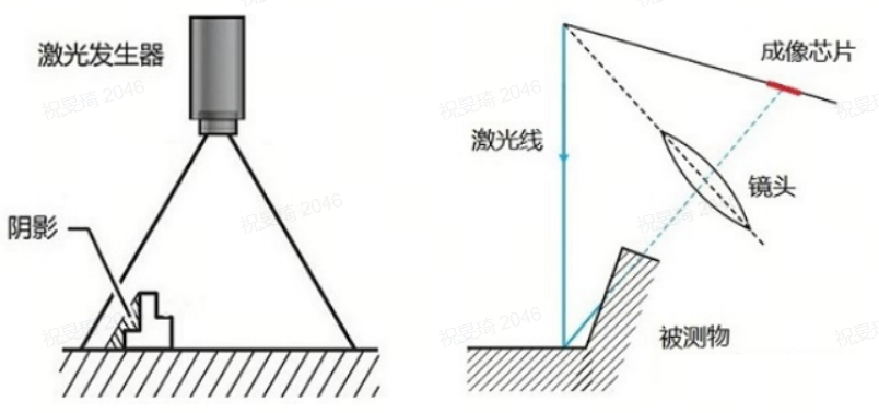
If the surface of the object being measured is uneven, in addition to optical obstruction, multiple reflections may also occur.
As shown in the figure below, ray 1 is the incident light that occurs on the surface of an object第1Secondary reflection, ray 2 is the second reflection of incident light on the surface of an object, and these two rays have different imaging positions on the detector.

As shown in the figure below, the red incident light undergoes two reflections on the surface of the object, and these two reflections have the same imaging position on the detector.

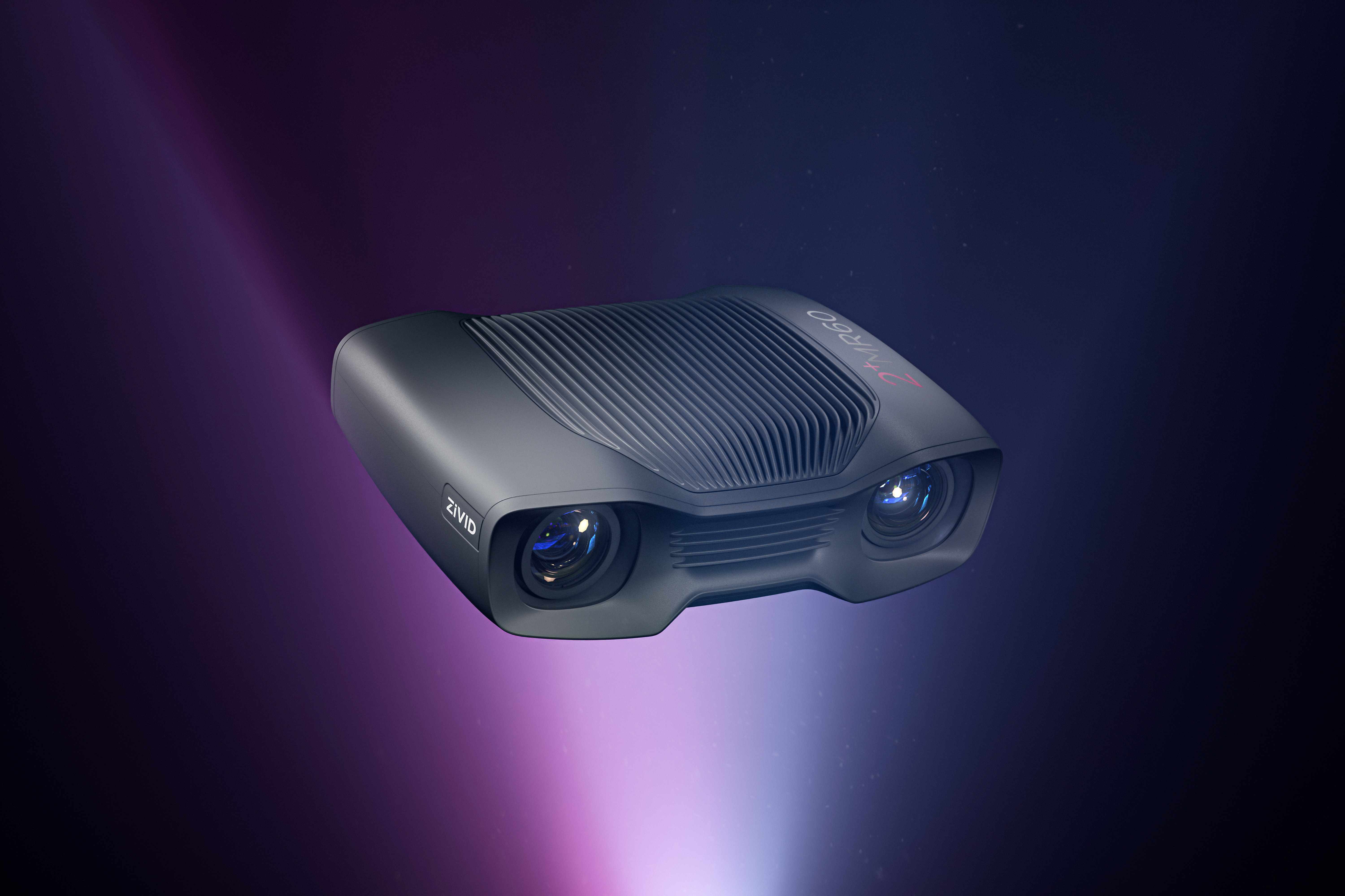
Zivid 2+ M60
Zivid 2+M60 from Haoai Intelligent AgentIt is a high-resolution robot fixed 3D+2D camera used for resolution, accuracy, and detail requirementshighThe application. This camera is the clearest and densest point cloud product among Zivid 3D cameras, capable of capturing up to 5000 points per square centimeter with a size accuracy of over 99.8%. All objects can be presented in their true form. For quality inspection and precise assembly tasks, it can easily observe every detail, feature, and defect. Capture the most stunning point cloud in just 100 milliseconds.
About Haoai Intelligent
Haoai Intelligent is the professional agent of German ZIVID in the field of 3D vision in China.
Haoai Intelligence focuses on providing comprehensive 3D machine vision solutions to help improve China's intelligent manufacturing level and industrial upgrading!
At present, we have a group of highly qualified 3D machine vision application engineers and algorithm development engineers, with complete machine vision project evaluation capabilities and underlying core algorithm development capabilities. Our 3D machine vision overall solution has been successfully implemented in multiple fields such as power batteries, automotive industry, consumer electronics, white goods, and rail transit inspection, accumulating rich experience in 3D machine vision project application and software development!
Haoai Intelligent's main products: 3D machine vision integrated solutions, including structured light 3D cameras, laser line scanning cameras, SICK 3D line laser contour sensors, TOF cameras, high-precision 3D measurement systems, visual guidance positioning systems, disordered grasping systems, etc. It can achieve functions such as flatness, height difference, positional measurement, concave convex defect detection, adhesive path detection, visual guidance robot polishing, visual guidance robot workpiece positioning and assembly, and workpiece disordered grasping.