-
E-mail
18083798558@163.com
-
Phone
18101455820
-
Address
No. 23 Haiwo Road, Guangling District, Yangzhou City
Jiangsu Ruyan Busbar Manufacturing Co., Ltd
Design and layout of 35KV tubular busbar trunking
Date: 2025-11-20Read: 36
35KV tubular busbar trunkingIt is a closed power transmission device composed of conductors, insulation layers, and metal tube shells, mainly used in high current transmission and distribution systems.
1. Tube type busbars are generally made of insulated tube cables.
2. Electrical conductors: oxygen free copper tubes (rods: current less than 630 amperes), pure aluminum alloy tubes, and aluminum alloy tubes.
3. The fully insulated shielded tubular busbar is constructed with cylindrical power capacitors. A voltage equalizing capacitor shielding layer and a main insulation layer are installed between the electrical conductor and the insulated wire cover. The surface layer is a metal material that is connected to the grounding grid to shield the geological structure. The total number of each layer should be calculated by the seller based on the equivalent working voltage and the design scheme of each enterprise, and combined with successful cases to clarify. The setting standard for shielding layer: to make the static electric field of each module of the tubular busbar uniform, stress free, especially at the ends, in order to reduce the charging and discharging along the surface layer at the top. For extruded insulated tubular busbars, only the inner semiconducting layer, main insulating layer, and outer semiconducting layer are available. The external semiconductor material layer is coated with metal material to shield the geological structure.
4. According to different insulation methods, different semiconductor devices can be selected for the shielding layer of voltage equalizing capacitors, such as forging solid insulation busbars using semiconductor material paper. Aluminum platinum is selected for the capsule type.
5. The metal material shielding grounding geological structure is composed of a copper foil semi pressed layer with a thickness of not less than 0.05mm, or can be covered with a thin copper mesh outside the non-conductive layer.
6. The raw material of the busbar generally used for grounding devices is made of copper core wire, and reasonable structural reinforcement must be carried out at the grounding point.
7. The main insulation raw material can be EPDM rubber, cross-linked polyethylene, epoxy resin adhesive, or PTFE fixed film.
35KV tubular busbar trunkingShould comply with the following specifications and standards:
GB 156-1993 standard voltage
GB 311.1-1997 Insulation Coordination for High Voltage Transmission and Transformation Equipment
GB/T 762-1996 Standard Current
GB/T 763-1990 Heating of AC High Voltage Electrical Appliances during Long Term Operation
GB/T 2706-1989 Test Method for Dynamic and Thermal Stability of AC High Voltage Electrical Appliances
GB 4208-1993 Degrees of Protection Provided by Enclosures (IP Code)
GB/T 5231-1985 Processed Copper - Chemical Composition and Product Shape
GB/T 11021-1989 Evaluation and Grading of Heat Resistance of Electrical Insulation
GB/T 16927.1-1997 High Voltage Test Techniques Part 1: General Test Requirements
GB/T 16927.2-1997 High Voltage Test Techniques Part 2: Measurement Systems
GB 50150-1991 Electrical Equipment Handover Test Standard for Electrical Equipment Installation Engineering
GB 50260-1996 Code for Seismic Design of Electric Power Facilities
The tubular busbar should be sturdy enough to support its own weight, as well as the forces generated by mechanical vibrations and potential earthquakes, and accumulated precipitation from outdoor exposure. In addition, it is necessary to consider the temperature changes caused by Ohmic heating, the thermal expansion caused by environmental temperature changes, and the magnetic force caused by high currents. To address these issues, flexible busbars have been developed, typically consisting of sandwich layers of thin conductors. These require structural frameworks or cabinets for installation.
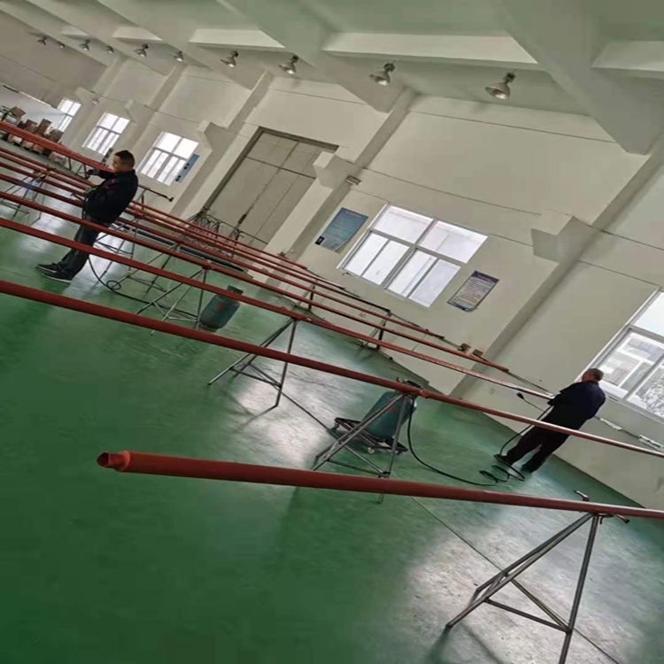
The distribution board divides the power supply into independent circuits in one location. The tubular busbar is a long busbar with a protective cover. They allow new circuits to branch along the route of the bus duct, rather than branching from the main power source at one location.