-
E-mail
email@jzpykj.com
-
Phone
18910378570
-
Address
3rd Floor, Building C, No. 6 Chaoqian Road, Changping District, Beijing
Beijing Jiuzhou Pengyue Technology Co., Ltd
Briefly describe the correct installation method of aerosol particle generator
Date: 2025-10-23Read: 1
In environmental monitoring equipment calibration, filter efficiency testing, respiratory protection research, and indoor air quality assessment, aerosol particle generators can stably generate aerosol particles with particle size and concentration (such as DOP, paraffin oil, NaCl, PSL microspheres, etc.), providing reproducible testing conditions for experiments. However, its performance depends not only on the device itself, but also closely related to the scientific installation. Incorrect installation may lead to unstable airflow, concentration deviation, equipment damage, and even safety hazards. Mastering the correct installation method of aerosol particle generators is the key to ensuring precise use.
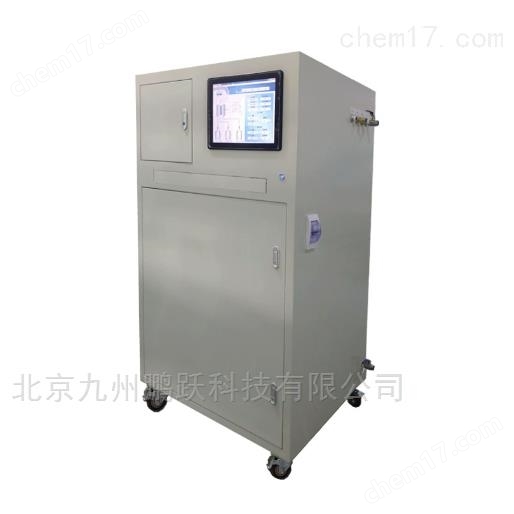
Step 1: Environmental assessment and location selection
Choose an installation environment with good ventilation, no strong electromagnetic interference, and suitable temperature and humidity. The equipment should be placed on a horizontal and stable experimental platform or support, away from high temperatures, humidity, and corrosive gases. Ensure there is sufficient space around (recommended to be ≥ 30cm in front and back) for heat dissipation, operation, and maintenance.
Step 2: Gas source connection
Most aerosol generators rely on compressed air or inert gases (such as nitrogen) as the driving gas source. Use clean, dry, oil-free compressed air, typically at a pressure of 0.1-0.3 MPa. Connect the air source to the generator inlet through a dedicated trachea (recommended PU or stainless steel material) to ensure that the joint is tight and leak free. It is recommended to install a filter pressure reducing valve at the gas source end to stabilize the pressure and remove moisture and impurities, in order to prevent clogging of the atomizing nozzle or contamination of the sample.
Step 3: Connection of aerosol output pipeline
Use pressure resistant and inert materials (such as PTFE polytetrafluoroethylene) hoses to connect the aerosol outlet of the generator to the testing system (such as ducts, filter test benches, or sampling chambers). The pipeline should be as short and straight as possible, avoiding sharp bends or folds to reduce particle deposition and turbulence. If long-distance transportation is required, it may be considered to install a constant velocity sampling probe or dilution system to maintain the representativeness of particulate matter.
Step 4: Wiring of Power Supply and Control System
Connect the power supply according to the equipment voltage requirements (usually AC220V or DC24V) and ensure good grounding. If equipped with external control interfaces (such as RS485, analog signals), connect them correctly to the data acquisition system or automatic control platform according to the instructions to achieve remote start stop and parameter adjustment.
Step 5: Trial operation and leakage inspection
After installation, conduct a no-load test without adding samples. Turn on the gas source and power supply, and check for any abnormal noise, vibration, or air leakage. Use bubble solution or leak detector to check the sealing of each interface. After confirming the accuracy, add an appropriate amount of aerosol medium (such as DOP oil), start the generator, and observe whether the atomization state is uniform and stable.