-
E-mail
3440125819@qq.com
-
Phone
18911397564
-
Address
No.1 Shangdi 10th Street, Shangdi Science and Technology Park, Haidian District, Beijing
Beijing Beiguang Jingyi Instrument Equipment Co., Ltd
How to use LCR impedance analyzer correctly
Date: 2025-12-03Read: 0
Guidelines for the Correct Use of LCR Impedance Analyzer
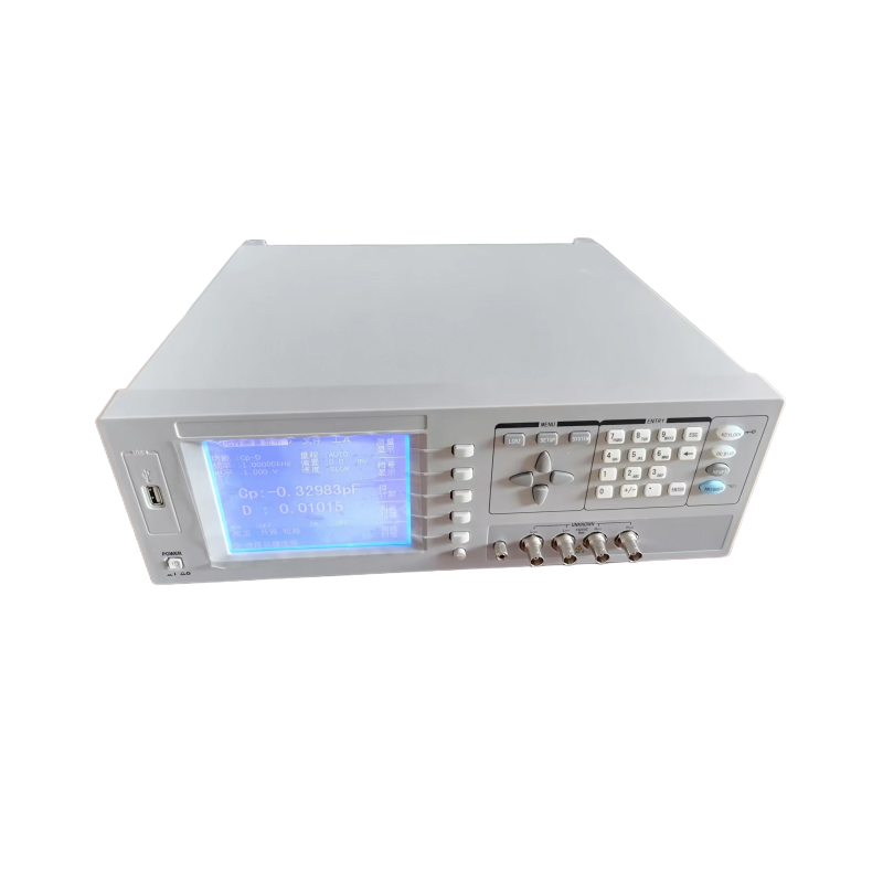
LCR impedance analyzer is a professional electronic measuring device, and its correct use requires following certain operating steps and precautions. The following will provide you with detailed instructions on how to use the LCR impedance analyzer correctly from multiple perspectives.
1、 Basic operating steps
Preparation phase
(1) Equipment inspection: Ensure that the power and connection wires of the tester are intact and the power switch is turned off. Check if the testing fixture or probe is clean to avoid poor contact caused by oxidation.
(2) Preheating treatment: After connecting the power supply, the instrument needs to be preheated for 10-30 minutes (refer to the instruction manual for specific time) to ensure that the internal circuit reaches thermal equilibrium and reduce measurement errors.
(3) Connecting peripherals: Connect external devices such as computers and printers according to testing requirements to ensure smooth data transmission.
Specific operational steps
(1) Startup and parameter settings:
Press the power button to start the instrument and wait for the self-test to complete
useSwitch the main measurement parameters (L/C/R) with the 'ZLCR' key, and select auxiliary parameters (Q value, D value, etc.) with the 'DQe' key
Set measurement frequency(Common range 1kHz, 100Hz, etc.) and signal level (10mV-2V), select appropriate parameters based on component characteristics
(2) Connect the component under test:
Connect the component to the test port and pay attention to the cleanliness of the pins
For components with shielded enclosures, their enclosures need to be grounded
Select series connection based on component impedance/Parallel equivalent circuit: series mode is used for low impedance (such as low value inductance), and parallel mode is used for high impedance (such as high value capacitance)
(3) Perform measurement:
Perform open and short circuit reset calibration to eliminate system errors
pressMeasure button or trigger key, observe screen data (main parameters L/C/R, secondary parameters Q/D, etc.)
Record data and save it. If continuous measurement is required, the automatic scanning mode can be turned on
2、 Advanced functional applications
constant voltage/Constant current mode: For voltage or current sensitive components such as MLCC and core inductors, select CV or CC mode to ensure measurement stability [1].
List scanning and comparison function: Set multiple frequencies/Automatic scanning of voltage level points, combined with a comparator to determine whether the component meets the standard.
Bias current control: measure the parameter changes of the component at a specific current with a bias power supply.
Segmented scanning function: Different frequency ranges can be set as different segmented scans, and different scanning points can be set in each segmentOSC level DC Bias、 Test time and other parameters.
3、 Precautions for use
Test environment:
Avoid strong electromagnetic interference
Maintain stable temperature and humidity
Calibration and maintenance:
Regularly open the circuit/Short circuit calibration
Pay attention to the cleanliness of the testing fixture
Parameter settings:
Select the appropriate equivalent circuit mode based on the characteristics of the tested object(Series/Parallel)
Set appropriate testing frequency and signal level
Safe operation:
Pay attention to insulation during high-voltage testing
Avoid overloading and damaging the instrument
Special precautions when measuring resistance:
Using the four line method(Four terminal measurement method) Eliminating the influence of test line resistance and contact resistance
Clean the contact points and remove the oxide layer
Select appropriate fixtures based on component packaging
4、 Practical application cases
Error Analysis of Inductance Measurement: A Certain Enterprise Used in the Production of Automotive Electronic ComponentsThe LCR tester measures a rod-shaped inductor with a nominal value of 4.9uH ± 15%, but the actual measured value is between 4.0uH and 4.15uH. Through analysis, it is found that the error is caused by improper testing frequency setting.
Resistance measurement technique: When measuring low resistance resistors using the four wire method, the measurement accuracy can be significantly improved. The specific steps include cleaning the contact points, selecting appropriate fixtures, and strictly following the four wire connection specifications.
Component reliability test: in multiple channelsIn the LCR testing plan, by setting reasonable compensation functions and using multi-channel testing equipment, the testing efficiency during component aging testing can be effectively improved.