|
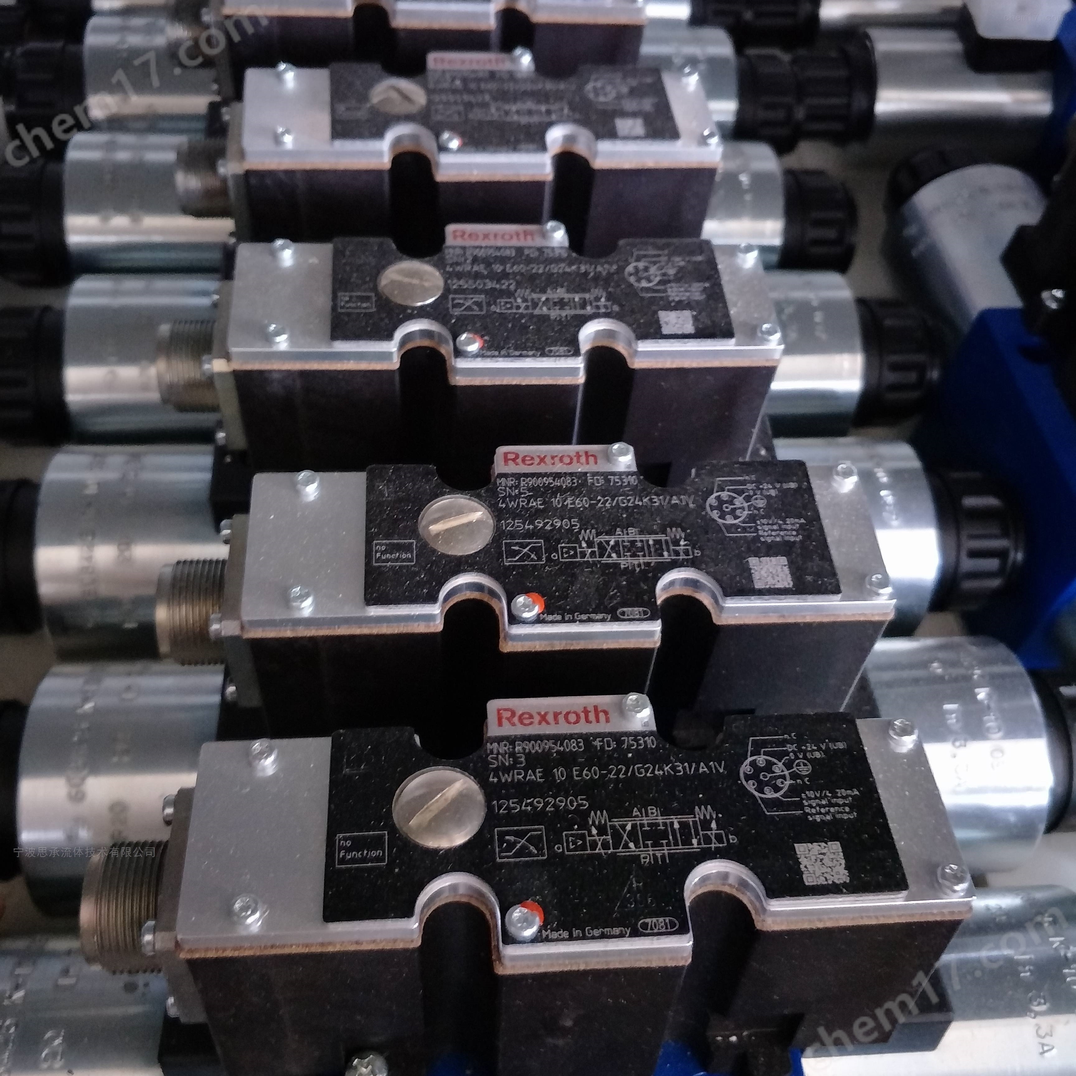
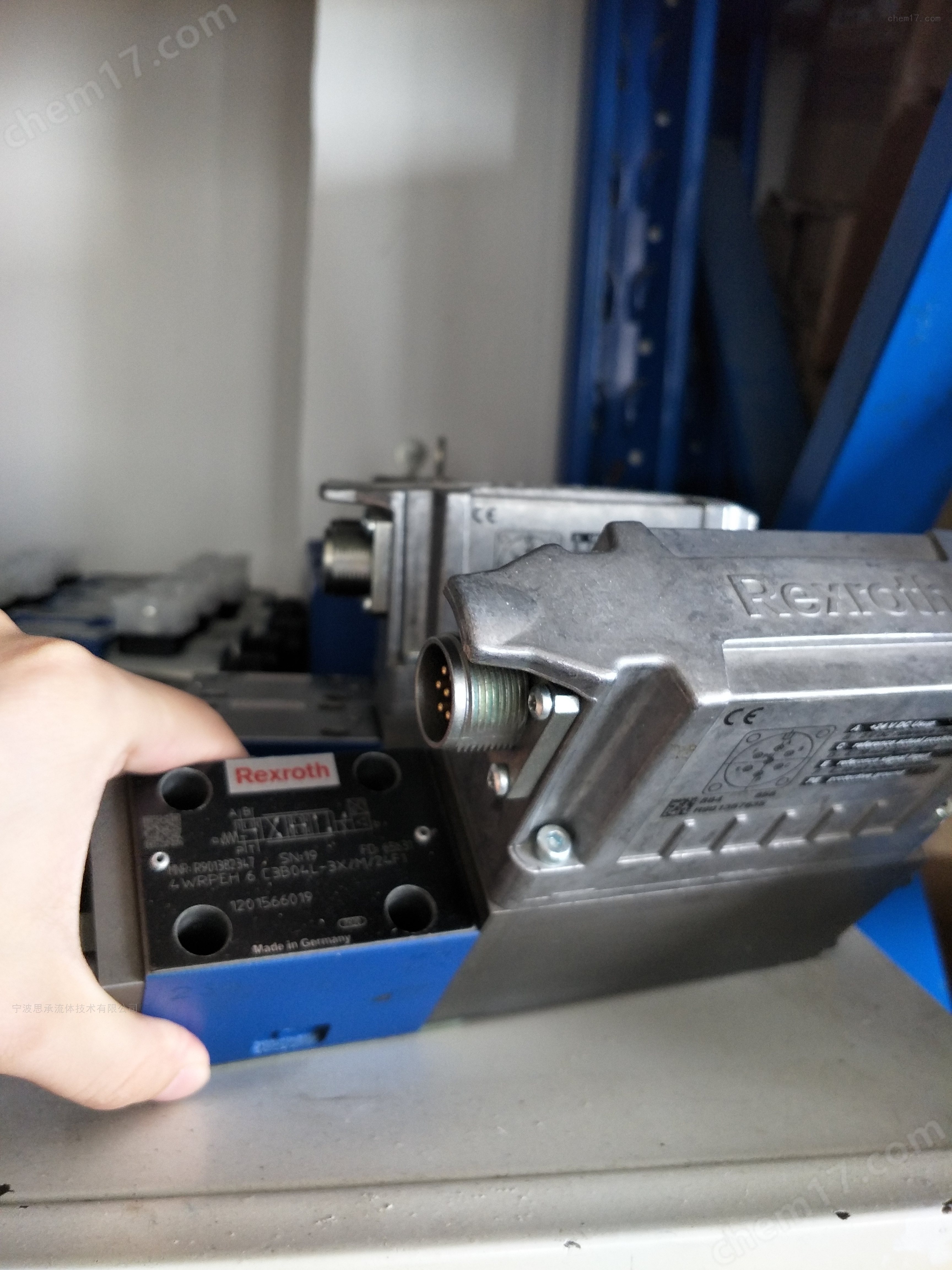
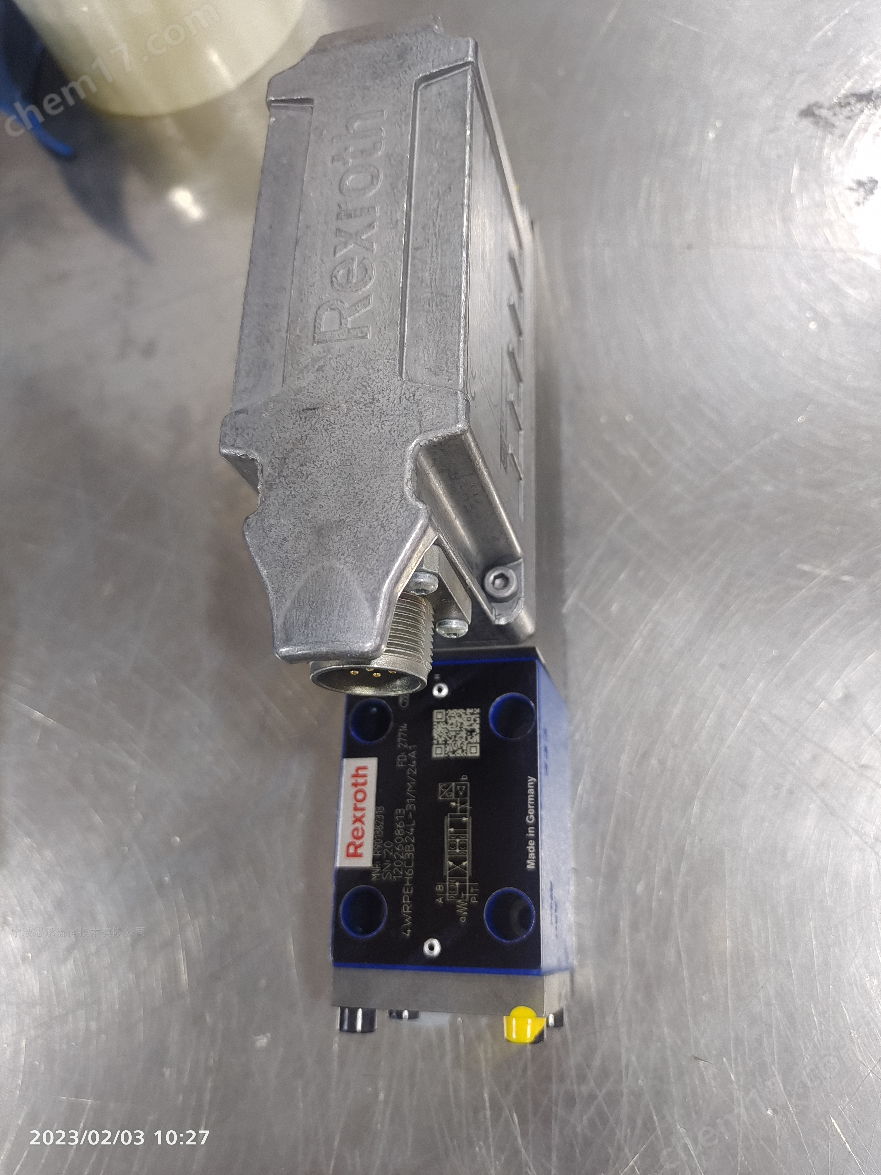
3785731 F12-110-MF-IV-Z-000-0000-P0
Pre-installation preparationConfirm that the model, specifications, electrical parameters, etc. of the proportional valve match the system requirements. Check the appearance of the proportional valve to ensure that there are no scratches, rust or other defects on the surface of the valve body and valve core, and that the seals are intact and undamaged. At the same time, prepare the necessary installation tools such as wrenches, screwdrivers, etc. Clean the pipelineBefore installation, it is necessary to thoroughly clean the pipeline and valve block. It is recommended to flush the pipeline with hydraulic oil to prevent impurities such as iron filings and oil stains from entering the valve, causing the valve core to become stuck or worn. Determine the installation location and directionChoose a suitable installation location, the ideal installation location is horizontal placement. If the proportional valve is installed on the actuator, it should be avoided that the valve core position is parallel to the acceleration direction of the actuator. When installing, ensure that the installation direction of the proportional valve is correct, usually referring to the arrow markings on the proportional valve. pipeline connectionConnect the proportional valve to the hydraulic system using connecting pipes, paying attention to the size and installation position of the pipes to ensure that the proportional valve can work smoothly. When installing the sealing gasket, make sure it is placed at the interface of the proportional valve and ensure the tightness of the sealing gasket to prevent hydraulic system leakage. When tightening the connecting bolts, avoid damaging the pipeline with excessive force. electrical connectionAccording to the electrical wiring diagram of the proportional valve, correctly connect the power supply, signal lines, etc. Ensure the power supply voltage is 24V, pay attention to the polarity of the wires, and avoid reverse connection. At the same time, signal lines should be wired separately from high-voltage lines and power lines to prevent electromagnetic interference
Mechanical zero adjustmentIn the absence of an input current signal, adjust the main valve core and displacement sensor to the middle position (zero position). It can be achieved by adjusting the setting screw to keep the feedback rod in the middle position, ensuring that the cylinder action tends to be stationary. Electrical zero adjustmentAfter the mechanical zero position adjustment is completed, adjust the electrical zero position. Input current signals of different sizes, observe the changes in output flow rate, and use corresponding debugging tools to adjust, so as to form a good correspondence between output flow rate and input current signal. Idle state debuggingIn the unloaded state, start the hydraulic system and observe the cylinder action through manual or electric directional valves to check whether the valve core action is smooth and whether the pressure and flow output are proportional to the input signal. If there are any abnormalities, further adjustments can be made to the set screws or related parameters. Load state debuggingUnder load conditions, observe parameters such as the amplitude, speed, and start stop sensitivity of the oil cylinder to determine if the proportional valve is working properly. If there are any issues, the performance of the proportional valve can be adjusted by changing the magnitude and direction of the control current by adjusting the potentiometer on the circuit board and integrated circuit. Parameter SettingsAccording to the working requirements of the system, set relevant parameters such as gain, bias, etc. Excessive gain can cause system overshoot, while insufficient gain can result in slow response. During debugging, the gain can be gradually increased from low gain (such as 50%) until the motion speed of the actuator is linearly related to the signal and there is no significant jitter. The dead zone setting is generally 5% to 10%, which can be fine tuned according to the smoothness of the actuator movement. 
high-precision controlEquipped with electrical position feedback, it can accurately control the flow, pressure, and direction of hydraulic oil, with high response sensitivity and small hysteresis. integrated designIntegrated electronic components (OBE) simplify external control circuits, improve system reliability and anti-interference capabilities. safe and reliableThe fault safety position of the control valve core is in the closed state, ensuring the safety of the system in abnormal situations. Energy-efficientNo need for pilot oil, reducing energy loss and improving system efficiency.
Industrial AutomationSuch as injection molding machines, die-casting machines, etc., used to achieve precise motion control and pressure regulation. construction machinerySuch as excavators, cranes, etc., can achieve precise directional control and flow control of hydraulic systems. Machine tool equipmentIn the hydraulic system of machine tools, it is used to control the movement of the worktable, the feed of cutting tools, and other actions.
This proportional directional valve is widely used in various applications that require precise hydraulic control due to its high precision, integration, and reliability.
|