-
E-mail
xxtkyb@126.com
-
Phone
18637357823
-
Address
Xiaoli Industrial Zone, West Section of Beihuan Road, Muye District, Xinxiang, Henan Province
Product Categories
Xinxiang Tianke Measurement and Control Instrument Co., Ltd

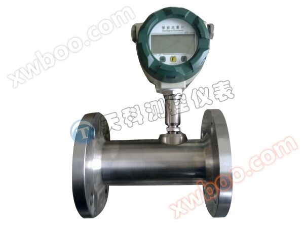
Plug in temperature and pressure compensation vortex flowmeter
NegotiableUpdate on 06/23
- Model
- Nature of the Manufacturer
- Producers
- Product Category
- Place of Origin
Overview
Overview: The LUGB/E vortex flowmeter is widely used in industries such as petroleum, chemical, metallurgical, thermal, textile, and papermaking for measuring and controlling superheated steam, saturated steam, compressed air, and general gases (oxygen, nitrogen, hydrogen, natural gas, coal gas, etc.), water, and liquids (such as water, gasoline, alcohol, benzene, etc.) Main technical indicators: nominal diameter (mm) 25
Product Details
Overview: The LUGB/E vortex flowmeter is widely used in industries such as petroleum, chemical, metallurgical, thermal, textile, and papermaking for measuring and controlling superheated steam, saturated steam, compressed air, and general gases (oxygen, nitrogen, hydrogen, natural gas, coal gas, etc.), water, and liquids (such as water, gasoline, alcohol, benzene, etc.)
Main technical indicators:
Nominal diameter (mm) | 25, 40, 50, 65, 80, 100, 125, 250, 200, 250, 300 (300-1000 plug-in type) |
Nominal pressure (MPa) | DN25-DN200 4.0 (>4.0 protocol supply), DN250-DN300 1.6 (>1.6 protocol supply) |
Medium temperature (℃) | Piezoelectric type: -40~260, -40~320; Capacitive: -40~300, -40~400, -40~450 (protocol ordering) |
Body material | 1Cr18Ni9Ti, (Other material agreement supply) |
Allow vibration acceleration | Piezoelectric type: 0.2g Capacitive type: 1.0-2.0g |
accuracy | ± 1% R, ± 1.5% R, ± 1FS; Insertion type: ± 2.5% R, ± 2.5% FS |
Range degree | 1:6~1:30 |
Supply Voltage | Sensor:+12V DC,+24V DC; Transmitter:+12V DC,+24V DC; Battery powered type: 3.6V battery |
output signal | Square wave pulse (excluding battery powered type): high level ≥ 5V, low level ≤ 1V; current: 4-20mA |
Pressure loss coefficient | Complies with JB/T9249 standard Cd ≤ 2.4 |
Explosion proof sign | Intrinsic safety type: Exd Ⅱ ia CT2-T5 Explosion proof type: Exd Ⅱ CT2-T5 |
protection grade | Regular IP65 Submersible IP68 |
environmental condition | Temperature -20 ℃~55 ℃, relative humidity 5%~90%, atmospheric pressure 86~106kPa |
Applicable Medium | Gas, liquid, steam |
Distance | Three wire pulse output type: ≤ 300m, two-wire standard current output type (4-20mA): load resistance ≤ 750 Ω |
Installation environment requirements:
1. Try to avoid strong electrical equipment, high-frequency equipment, and strong switching power supply equipment as much as possible. The power supply of the instrument should be separated from these devices as much as possible.
2. Avoid direct effects from high-temperature heat sources and radiation sources. If installation is necessary, insulation and ventilation measures must be taken.
3. Avoid high humidity and strong corrosive gas environments. If installation is necessary, ventilation measures must be taken.
4. Vortex flow meters should be avoided from being installed on pipelines with strong vibration as much as possible. If installation is necessary, pipeline fastening devices must be installed at 2D upstream and downstream locations, and anti vibration pads must be added to enhance the anti vibration effect.
5. The instrument should be installed indoors, and attention should be paid to waterproofing when installing outdoors. Special attention should be paid to bending the cable into a U-shape at the electrical interface to prevent water from entering the amplifier housing along the cable.
6. There should be ample space around the instrument installation point for wiring installation and regular maintenance.
Installation steps for plug-in vortex flowmeter:
1. Use gas welding to create a circular hole slightly smaller than 100mm on the pipeline, and remove any burrs around the hole to ensure smooth rotation of the measuring head
2. Weld the flange provided by the manufacturer at the circular hole of the pipeline, with the flange axis perpendicular to the pipeline axis.
3. Install the ball valve and sensor onto the welded flange.
4. Adjust the screw to ensure that the insertion depth meets the requirements (ensuring that the center axis of the probe coincides with the center axis of the pipeline), and the fluid flow direction must be consistent with the indicated arrow on the directional marker.
5. Tighten the screws on the cover evenly. (Note: The tightness of the gland determines the sealing degree of the instrument and whether the screw can rotate)
6. Check if each step is completed properly, slowly open the valve and observe if there is any leakage (special attention should be paid to personal safety). If there is any leakage, please repeat steps 5 and 6.