- Phone
-
Address
No. 1-3, Xinchengda Industrial Park, Dongxihu Taiwan Business Investment Zone (San Dian), Wuhan City
Product Categories
Wuhan Defu Electric Co., Ltd
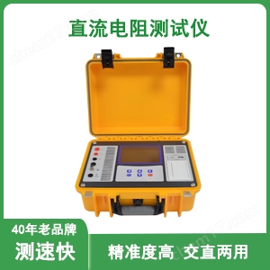
Multi channel DC resistance tester
NegotiableUpdate on 05/06
- Model
- Nature of the Manufacturer
- Producers
- Product Category
- Place of Origin
Overview
When testing inductive samples (such as transformer windings) with a multi-channel DC resistance tester, the wires should not be immediately disconnected after turning off the power. The instrument should be allowed to discharge automatically for at least 20 seconds (some instruments may have a buzzing alarm prompt), otherwise the back electromotive force of the inductor may endanger personal safety.
Product Details
1Multi channel DC resistance testerPreparation before use
environment check
Ensure a dry and ventilated working environment with a temperature range of 0-40 ℃ and humidity ≤ 80%, and keep away from strong electromagnetic interference sources such as welding machines and high-power motors.
The table on which the instrument is placed should be stable to avoid vibration affecting measurement accuracy.
Equipment inspection
Check if the power cord is intact (without damage or breakage) and if the plug and socket are in good contact.
Turn on the power switch of the instrument, confirm that the screen display is normal (no garbled text, black screen), and the button response is sensitive.
Check that the test wires (current wires, voltage wires) are not broken or short circuited, and that the clamping force of the crocodile clip or test probe is normal.
Processing of tested equipment
The tested equipment (such as transformer windings) needs to be powered off and fully discharged, especially capacitive equipment that needs to be discharged with a discharge rod for 3-5 minutes to ensure the release of residual charges.
Clean the wiring terminals of the tested winding, remove the oxide layer, oil stains or dust (can be lightly wiped with fine sandpaper), and ensure good contact between the test wire and the terminals.
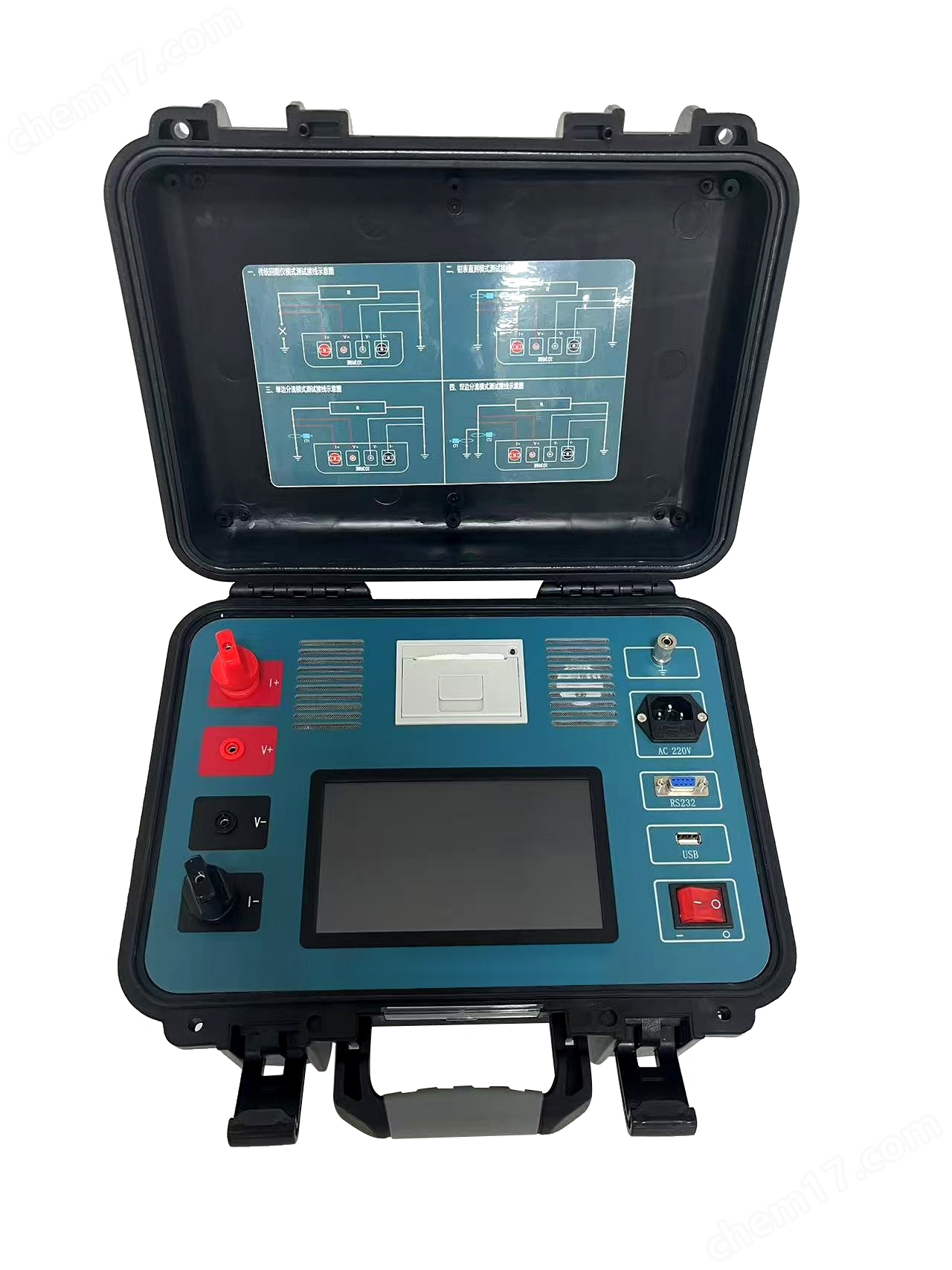
2、 Wiring method for multi-channel DC resistance tester (four terminal measurement method)
Four terminal method principle
By separating the current circuit and voltage circuit, the influence of contact resistance and lead resistance is eliminated to ensure measurement accuracy.
Wiring steps
Current output terminal (red thick line):
Connect "I+" to the outer side of one end of the tested winding (current inflow end).
Connect "I -" to the outer side of the other end of the tested winding (current outflow end).
Voltage measurement terminal (black thin line):
Connect the "V+" to the inner side of one end of the tested winding (close to the winding body, close to the inner side of the current line).
Connect the "V -" to the inner side of the other end of the tested winding.
Example: When measuring the resistance of phase A in the low-voltage winding of a transformer:
I+connected to the outer side of the A-phase terminal, V+connected to the inner side of the A-phase terminal;
I - Connect to the outside of the neutral terminal, V - Connect to the inside of the neutral terminal.
Attention: The current line and voltage line should not be reversed, otherwise it may cause measurement deviation or instrument protection.
3、 Parameter settings
Test current selection
Small resistance (0.01~1 Ω): Choose a larger current (such as 10A~100A) to reduce measurement errors (the larger the current, the stronger the voltage signal, and the stronger the anti-interference ability).
High resistance (1-100 Ω): Choose a smaller current (such as 1A~10A) to avoid overheating of the tested winding (especially for thin wire windings, high current may cause excessive temperature rise and change the resistance value).
Automatic Range: Novices are advised to choose "Automatic Range", as the instrument will automatically switch to the appropriate range based on the measured resistance; After familiarizing oneself with the operation, the "manual range" can be used to improve efficiency.
Measurement time setting
Fast mode (1-3 seconds): default mode, suitable for environments with minimal interference.
Slow mode (5-10 seconds): Switch to this mode when there is high environmental interference, take the average of multiple samples, and improve stability.
Temperature compensation (optional)
Some instruments support inputting the temperature of the tested device and automatically converting it to the resistance value at the standard temperature (such as 20 ℃). It is necessary to know the temperature coefficient of the winding material (such as copper wire α=0.00393/℃).

4、 Measurement operation
Start measurement
After completing the wiring and setting the parameters, press the "Measure" button (or "Start" button) on the instrument, and the instrument will automatically output the set current. The screen will display the measured value in real-time (unit: Ω or m Ω).
Attention: Do not touch the test line or the tested terminal during the measurement process, and do not plug or unplug the test line.
Data reading and recording
After the screen displays stable values (with a few decimal places no longer jumping), record the measurement results.
Some instruments support automatic data locking, and pressing the "Save" button can store it in the internal memory (usually with a storage capacity of 250 times, data will not be lost after power failure).
Exception handling:
If "0.000" or "overflow" (such as "OL") is displayed, check whether the wiring is loose, whether the current level is too low (when the resistance is high) or too high (when the resistance is low), and whether the tested winding is open/short circuited.
5、 Measurement completion and equipment maintenance
stop measuring
Press the "stop" button to stop the instrument from outputting current. After the screen displays the "standby" state, remove the test line.
If it is necessary to measure other windings of the same equipment (such as transformer B-phase and C-phase), repeat the wiring measurement steps to ensure that the measurement conditions for each winding are consistent (as in the same current range).
Discharge treatment
Multi channel DC resistance testerWhen testing inductive test samples (such as transformer windings), the wires should not be immediately disconnected after turning off the power. The instrument should be allowed to discharge automatically for at least 20 seconds (some instruments may have a buzzing alarm prompt), otherwise the back electromotive force of the inductor may endanger personal safety.
Equipment maintenance
Regular calibration: Use standard resistors for calibration every 6 months, and maintenance is required when the error is greater than ± 0.5%.
Storage conditions: Keep in a dry, dust-free, non corrosive gas environment, avoid direct sunlight or drastic temperature changes.
Battery maintenance: If the instrument has a built-in battery and the battery is low, it will display "Low battery, please charge". Use a dedicated charger to charge and avoid overcharging or overdischarging.
6、 Safety precautions
Operational Security
Before testing, it is necessary to ensure that the equipment is powered off and insulated tools are used during discharge. It is forbidden to touch exposed conductors.
The instrument and the tested equipment are grounded together to avoid the risk of electric shock caused by potential difference.
Wear insulated gloves and goggles, and set up a warning area during high-voltage testing.
Polarity correct
Red (+) and black (-) should not be reversed to avoid data errors or instrument damage.
Long wire measurement
If long wires are required, use the four wire method (Kelvin connection) to eliminate the influence of lead resistance.