-
E-mail
njndzt@163.com njndzt@vip.163.com
-
Phone
15850692228
-
Address
No. 29 Lanxia Road, Moling Industrial Park, Jiangning District, Nanjing City, Jiangsu Province
Product Categories
- Four wheel trailer drilling rig (1-300 meters)
- 6、 Grouting equipment, drilling grouting series matching (please click to enter)
- BW150 mud pump, grouting pump, grouting pump
- Service Philosophy
- BW160/10 mud pump, grouting pump, grouting pump
- 2. Drilling rig assembly four corner frame drilling tower (without trailer, four-wheel trailer) (1-300 meters) (recommended)
- 200-300 meter drilling rig (click to enter)
- 100-1300 meter series automotive drilling rig
- Anchor drilling rig (click to enter)
- Tunnel drilling rig (click to enter)
- BW200A mud pump, grouting pump, grouting pump
- 9、 Complete set ordering, export, freight, service concept, construction cases
- 8、 Drilling rig and mud pump accessories
- 1-180 meter drilling rig (click to enter)
- Fully hydraulic multifunctional drilling rig (click to enter)
- Crawler drilling rig (30-300 meters)
- Roller drill bit
- Various drilling tools
- wire line coring
- 7、 Lightweight drilling rig (small drilling rig within 1-50 meters, for soil and rock core sampling, drilling, grouting, environmental impact assessment, geological survey) (please click to enter)
- 3、 Mud pump, grouting pump, mortar pump, grouting pump, mixing machine series (please click to enter)
- training
- Complete set ordering
- BW600 mud pump, grouting pump, grouting pump
- 3. Drilling rig assembly four corner frame drilling tower (without trailer, four-wheel trailer) (300-2000 meters) (recommended)
- 4. Crawler drilling rig, equipped with self-propelled crawler chassis and drilling tower (optional with four corner frame and hydraulic drilling tower) (1-2000 meters) (recommended)
- Mixing machine, mixing bucket, mixing
- Other drilling equipment matching
- 5. 9-meter, 13 meter, 18 meter, and 23 meter high cross shaped dual-purpose drilling rig tower
- Composite drill bit (with or without core)
- Diamond drill bit, reamer
- 1. Drilling rig assembly tripod drilling tower integrated machine (without trailer, two wheel trailer)
- Construction Case
- BW100-5 cement mortar pump (grouting pump, grouting pump) (a new generation of high-pressure and high displacement mortar pump with large sand particles)
- BWS200-10 cement mortar pump (grouting pump, mud pump) (three cylinder) (high pressure, high displacement, large sand mortar pump)
- 5、 Static cone penetration tester locomotive series (equipment, instruments, probe rods, probes and other accessories) (please click to enter)
- Small Fried Dough Twists drill (manual), portable dynamic probe, micro sampler, Luoyang shovel
- ZBI-150 grouting pump, grouting pump, mud pump (infinitely variable speed, three cylinder, high pressure)
Nanjing Nandi Drilling Machinery Co., Ltd

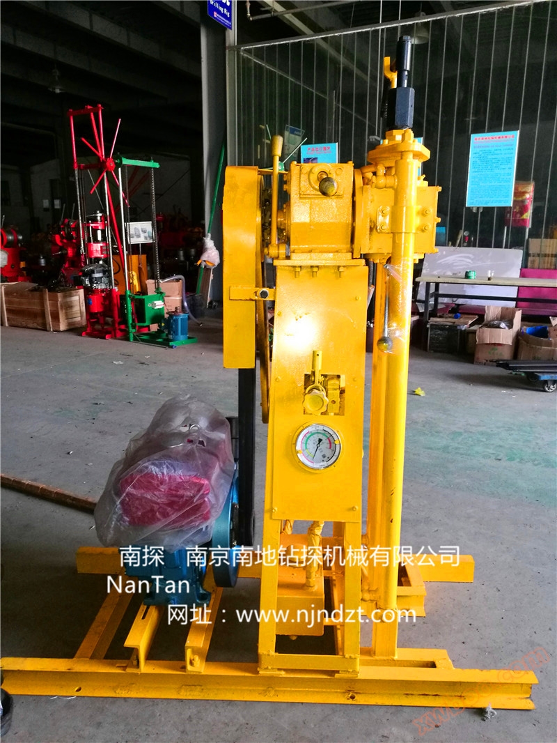
MD series anchoring drilling rig (30-120m)
NegotiableUpdate on 04/29
- Model
- Nature of the Manufacturer
- Producers
- Product Category
- Place of Origin
Overview
The MD series slope anchoring engineering drilling rig is suitable for the construction of large tonnage prestressed anchor rod support holes, drainage holes, and geological disaster control projects such as hydropower station engineering, railway, and highway slope anchoring. The drilling rig is divided into three parts: pump station, control panel, and main engine. The split structure makes relocation and installation quick and convenient; Remote control is possible, improving the working environment for employees. The 1200mm propulsion frame is suitable for working conditions with small construction space. This drilling rig has the following characteristics: 1. Compact structure, light weight, strong disassembly, easy to relocate and install. Strong adaptability to construction sites, more suitable for construction on scaffolding. 2. The power head of the drilling rig has high torque, long stroke, and high drilling efficiency. 3. Equipped with specialized follow-up drilling tools (drill pipe, casing, eccentric drill bit, etc.), the casing is used to protect the wall and drill holes in unstable formations, while the conventional ball tooth drill bit is used for final drilling. High drilling efficiency and good drilling quality. 4. The drilling angle range of the drilling rig is large, from 10 ° upward to 90 ° downward; Or it can be modified to tilt up 90 ° to tilt down 10 °. The carriage can slide forward and backward along the chassis, and the drilling positioning is convenient and reliable. The center of the drilling rig is low, making it convenient to raise and lower the drilling tools. 5. Fully hydraulic control, easy and flexible operation, time-saving and labor-saving. 6. Optional orifice dust collection device can be selected to reduce environmental pollution and improve the working environment. model MD-50A MD-60A MD-80......
Product Details
The MD series slope anchoring engineering drilling rig is suitable for the construction of large tonnage prestressed anchor rod support holes, drainage holes, and geological disaster control projects such as hydropower station engineering, railway, and highway slope anchoring. The drilling rig is divided into three parts
Divided into: pump station, control panel, and main engine. The split structure makes relocation and installation quick and convenient; Remote control is possible, improving the working environment for employees. The 1200mm propulsion frame is suitable for working conditions with small construction space.
This drilling rig has the following characteristics:
1. Compact structure, light weight, strong disassembly, easy to relocate and install. Strong adaptability to construction sites, more suitable for construction on scaffolding.
2. The power head of the drilling rig has high torque, long stroke, and high drilling efficiency.
3. Equipped with specialized follow-up drilling tools (drill pipe, casing, eccentric drill bit, etc.), the casing is used to protect the wall and drill holes in unstable formations, while the conventional ball tooth drill bit is used for final drilling. High drilling efficiency and good drilling quality.
4. The drilling angle range of the drilling rig is large, from 10 ° upward to 90 ° downward; Or it can be modified to tilt up 90 ° to tilt down 10 °. The carriage can slide forward and backward along the chassis, and the drilling positioning is convenient and reliable. The center of the drilling rig is low, making it convenient to raise and lower the drilling tools.
5. Fully hydraulic control, easy and flexible operation, time-saving and labor-saving.
6. Optional orifice dust collection device can be selected to reduce environmental pollution and improve the working environment.
|
model
|
MD-50A
|
MD-60A
|
MD-80A
|
MD-100A
|
MD-120A
|
|
Drilling diameter (mm)
|
Φ85~Φ160
|
Φ90~Φ185
|
Φ100~Φ210
|
Φ130~Φ250
|
Φ150~Φ250
|
|
Drilling depth (m)
|
60~40
|
80~50
|
80~50
|
100~60
|
120~80
|
|
Drill pipe diameter (mm)
|
Φ73、Φ89
|
Φ73、Φ89、Φ102
|
Φ89、Φ102、Φ114
|
Φ89、Φ102、Φ114
|
Φ89、Φ102、Φ114
|
|
Drill pipe inclination angle (°)
|
-10~90
|
-10~90
|
-10~90
|
-10~90
|
-10~90
|
|
Rotary output speed (r/min)
|
10. 25, 45, 60, 100, 130
|
12. 25, 45, 60, 100, 125
|
16. 30, 38, 55, 75, 105
|
10. 20, 36, 48, 75, 100
|
15. 30, 30, 45, 60, 90
|
|
Rotary output torque (N.m)
|
2000
|
2700
|
4200
|
5500
|
6500
|
|
Rotary travel (mm)
|
1800
|
1800
|
1800
|
1800
|
1800
|
|
Propulsion frame for process (mm)
|
600
|
600
|
600
|
600
|
600
|
|
Rotary lifting force (KN)
|
42.5
|
42.5
|
65
|
65
|
65
|
|
Rotary lifting speed (m/min)
|
Adjustable from 0 to 1.5, 1.5, 6, 7.5
|
Adjustable from 0 to 1.65, 1.65, 5.8, 7.5
|
0~1 adjustable, 1, 7.5, 8.5
|
0~1 adjustable, 1, 7.5, 8.5
|
0~1 adjustable, 1, 7.5, 8.5
|
|
Rotary pressure (KN)
|
26
|
26
|
33
|
33
|
33
|
|
Rotating device pressurization speed (m/min)
|
Adjustable from 0 to 2.5, 9.5, 12
|
Adjustable from 0 to 2.7, 9.5, 12
|
0-2 adjustable, 14.5, 16.5
|
0-2 adjustable, 14.5, 16.5
|
0-2 adjustable, 14.5, 16.5
|
|
Input power (KW)
|
18.5+1.5+0.15
|
22+1.5+0.15
|
30+1.5+0.25
|
37+1.5+0.25
|
45+1.5+0.25
|
|
Weight (kg)
|
1200
|
2300
|
2600
|
2800
|
3000
|
|
Vertical construction state appearance (length x width x height mm)
|
2000×700×3150
|
2300×650×3400
|
2200×650×3400
|
2200×650×3400
|
2200×650×3400
|
|
Transportation status appearance (length x width x height mm)
|
3200×700×1300
|
3400×650×1400
|
3400×650×1500
|
3400×650×1500
|
3400×650×1500
|
Similar Product Recommend