-
E-mail
940009794@qq.com
-
Phone
1395802750715968172475
-
Address
No. 159, Nanshan North Road, Renhe Street, Yuhang District, Hangzhou City
Product Categories
Hangzhou Weige Electronic Technology Co., Ltd

Internal combustion engine testing system for electric dynamometer
NegotiableUpdate on 04/22
- Model
- Nature of the Manufacturer
- Producers
- Product Category
- Place of Origin
Overview
Host introduction: The internal combustion engine testing system has the following characteristics: using the latest microcontroller as the core of acquisition and control, the microcontroller comes with high-speed 12 bit A/D and D/A
Product Details
1、 Overview:
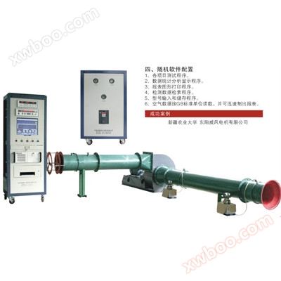
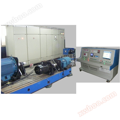
The internal combustion engine testing system of the electric dynamometer is a product developed by "Weige" based on years of continuous research on internal combustion engine bench tests and updates to the engine testing system. The internal combustion engine testing system has the following characteristics:
⑴ Adopting the latest microcontroller as the core for acquisition and control, the microcontroller comes with high-speed 12 bit A/D and D/A, greatly reducing the number of components and circuit board size, while also greatly improving reliability and making maintenance easy.
Combine the control core with the computer to display speed, torque, and output power.
2、 Composition of internal combustion engine testing system:
|
Internal combustion engine measurement and control system cabinet
|
One (installed together with the computer on the instrument cabinet)
|
|
● High speed electric dynamometer
|
One (installed on a cast iron platform)
|
|
Industrial control computer
|
One (installed together with the measurement and control system on the instrument cabinet)
|
|
● LCD display
|
One (installed on the system cabinet of the laboratory)
|
|
● Install dynamometer cast iron flat plate
|
One piece (installing dynamometer and engine)
|
|
● Throttle actuator
|
One (installed near the engine)
|
|
● Dynamic torque sensor
|
One (installed between dynamometer and engine)
|
3、 Technical performance and parameters of internal combustion engine testing system:
(1) Power measurement:
1. Speed section:
Measurement range: 0-12000r/min, measurement accuracy: 0.1% ± 1r/min;
2. Torque section:
Measurement range: 0-15NM; measurement accuracy: matched with the dynamometer, the overall accuracy is ≤± 0.4% F · S
3. Power section:
The power is a calculated value, which is calculated by the computer and displayed directly on the screen. The calculation formula is as follows:
Power=Speed (r/min) × Torque (N · m)/9550 (kW)
(2) Fuel consumption measurement: (omitted)
1. Fuel consumption measurement:
The fuel consumption measurement of the internal combustion engine testing system is completed using a weight based fuel consumption meter or a volume based fuel consumption meter. The main technical parameters for fuel consumption measurement are as follows:
⑴ Weight based fuel consumption meter:
a. Measurement accuracy and range:
|
measurement range
|
Display digits
|
Weighing resolution
|
称重精度
|
Measurement time range
|
Timing accuracy
|
|
0~50g
|
4 people
|
0.01g
|
≤0.5%F·S
|
2~250s
|
0.01s
|
|
0~100g
|
5 people
|
0.02g
|
|||
|
0~200g
|
0.05g
|
≤0.3%F·S
|
|||
|
0~500g
|
4 people
|
0.1g
|
|||
|
0~1kg
|
5 people
|
0.2g
|
≤0.2%F·S
|
||
|
0~2kg
|
0.5g
|
||||
|
0~5kg
|
4 people
|
1g
|
b. Display: fuel consumption in 5 digits, time in 3 digits; Synchronize and refresh fuel consumption and time every second; A 20 bit light column monitors the liquid level in the oil cup in real-time.
⑵容积法油耗仪:
a. 油耗测量范围:共分六档量程: 5ml、5ml、5ml、10ml、10ml、20ml;
Customized for other specifications.
b. Measurement accuracy: better than ± 0.5% of the full-scale value.
c. Time measurement range: 0-99.99 seconds, with an accuracy of 0.01 seconds.
d. Display: Fuel consumption volume 2 digits, time 4 digits; Seven light-emitting diodes monitor the oil level.
2. Fuel consumption and fuel consumption rate:
The fuel consumption and fuel consumption rate are calculated values, and their calculation formulas are as follows:
⑴ Weight method: Fuel consumption=3.6 × Fuel consumption weight (g) ÷ Fuel consumption time (s) (kg/h)
Volumetric method: Fuel consumption=3.6 x Fuel consumption volume (ml) x Gasoline density (g/ml) ÷ Fuel consumption time (s) (kg/h)
⑵ Fuel consumption rate=(1000 x fuel consumption ÷ measured power) (g/kW · h)
(3) Temperature and pressure measurement:
Only display measurement values on the PC. The main technical indicators of the internal combustion engine parameter measurement module are as follows:
|
sensor type
|
measurement range
|
measurement accuracy
|
Remarks
|
|
Type K thermocouple
|
0~999℃
|
±1%F·S
|
Total measurement accuracy after connecting with sensors
|
|
T-type thermocouple
|
0~150℃
|
±1%F·S
|
|
|
transmitter
|
4~20mA
|
±0.5%F·S
|
Due to the different installation dimensions of temperature sensors and pressure transmitters for various internal combustion engines, users must specify the connection dimensions when ordering.
(4) Control of dynamometer load and throttle position:
⑴ Control method for load of dynamometer:
The constant torque control method has a constant accuracy better than 0.5% F · S
The constant speed control method has a constant accuracy better than ± 5r/min
⑵ Throttle position:
The internal combustion engine testing system adopts a throttle actuator, linear, with a full stroke of 35mm, a full stroke time of less than 3s, a tensile force of ≥ 3.5kgf, an opening display value of 0-100%, and a measurement accuracy of better than 1%.
The throttle control method is constant position control, with a constant accuracy better than 1% F · S.
(5) System alarm and control:
⑴ Overspeed alarm protection function:
The overspeed setting can be set arbitrarily between 0 and 11999r/min, and the control action after the engine overspeed alarm is controlled by the PC. When the engine speed exceeds the set speed limit, the overspeed indicator light will light up, the buzzer will sound an alarm, and the throttle actuator will return to zero.
⑵ Overload protection function:
The overload setting can be arbitrarily set between 0 and the full range torque of the dynamometer, and the overload control action of the engine is controlled by the PC. When the engine torque exceeds the set speed limit, the overload indicator light will light up, the buzzer will sound an alarm, and the load of the dynamometer and the ignition contact of the engine will be cut off. At the same time, the throttle actuator will return to zero position.
⑷ Over limit alarm protection function for setting parameters of the dynamometer:
Set controller panel parameters
⑸ Emergency stop function:
Press the "emergency stop" button to cut off the load, disconnect the engine ignition contact, and return the throttle actuator to zero.
(6) Normal working conditions of the instrument:
⑴ Environmental temperature: 0-40 ℃
⑵相对湿度: ≤90%R·H
⑶电源: AC220V/380V±10%/50Hz
4、 Internal combustion engine testing system in internal combustion engine laboratory
The internal combustion engine testing system is connected between each unit through serial communication, thereby minimizing the need for connecting cables. Therefore, it greatly improves the reliability of the system and greatly reduces the complexity and cost of future maintenance services. And between each unit and the PC, data is transmitted bidirectionally through a communication controller. Power isolation is implemented between each unit to effectively prevent damage to other units caused by damage to one unit's components
1. Control of dynamometer and throttle:
The internal combustion engine testing system controls the load and throttle position of the dynamometer through the microcontroller of the measurement and control unit. The adjustment of the dynamometer load and throttle opening can be achieved by manually adjusting the setter or by sending control values to the measurement and control microcontroller through a PC. The internal combustion engine testing system can achieve load control of AC electric dynamometer and adjustment of engine throttle through different digital PID control modes.
⑴ Load control of dynamometer:
In order to maximize the ability of the dynamometer to meet various engine testing requirements, the control unit of the internal combustion engine testing system has adjustment characteristics (working mode) for users to adjust
⑵ Adjustment of engine throttle:
The internal combustion engine testing system adopts a throttle actuator, and the throttle control method is constant position control, with a constant accuracy better than 1% F · S.
⑶ Constant throttle position control:
By controlling the PID regulation of the microcontroller, the throttle position of the engine is stabilized at the set value. This method can be combined with any of the control methods of the electric dynamometer mentioned above to adjust the position of the throttle and the load of the dynamometer. The specific combination is chosen by the user according to the experimental requirements.
⑷ Alarm protection control:
In the measurement and control unit, relays and logic circuits are used to form engine overspeed alarm protection, dynamometer overcurrent and overpower protection, and emergency stop circuits. This fully considers that even if the PC and microcontroller of each unit in the testing system fail due to various reasons, the system can still reliably protect the engine and dynamometer. Due to the harsh environment of engine testing, such a design is essential.
2. Communication control unit:
The communication control unit is responsible for controlling the bidirectional data transmission between various parts of the entire system, while isolating each unit of the system from common power and ground. In this way, even if the components of a certain unit are damaged, it will not cause other units to be damaged as well.
5、 Test environment requirements:
Power supply voltage: 380V ± 10%, ambient temperature: 0-40C ° C, relative humidity:<90%
Grounding requirement: There must be an independent grounding wire
Power supply system connection: manually operated disconnect device.
Similar Product Recommend