- Phone
-
Address
Building 6, Optics Valley Electromechanical Industrial Park, No. 84 Gaoxin 5th Road, Donghu New Technology Development Zone, Wuhan City, Hubei Province
Product Categories
Wuhan Ultra High Voltage Power Technology Co., Ltd

FM series resonance
NegotiableUpdate on 05/06
- Model
- Nature of the Manufacturer
- Producers
- Product Category
- Place of Origin
Overview
The UHV-135kVA/108kV series resonance scheme device has protection functions such as overvoltage, overcurrent, zero start, and system detuning (flashover). The entire device is lightweight and easy to use on site, using DSP platform technology
Product Details
UHV-135kVA/108kV series resonance schemeMeet the scope of the test sample
1、10kV/300mm2AC withstand voltage test for 3km cable, capacitance ≤ 1.1265 μ F, test frequency 30-300Hz, test voltage 22kV, test time 5min.
2. AC withstand voltage test for 10kV switch and other substation equipment, with a test frequency of 30-300Hz, a test voltage not exceeding 42kV, and a test time of 1 minute.
3、35kV/300mm2AC withstand voltage test for 1km cable, capacitance ≤ 0.1945 μ F, test frequency 30-300Hz, test voltage 52kV, test time 60min.
4. AC withstand voltage test of 35kV/31500kVA main transformer, capacitance ≤ 0.02 μ F, test frequency 45-65Hz, test voltage 68kV, test time 1min.
5. AC withstand voltage test for 35kV switches and other electrical equipment, with a test frequency of 30-300Hz, a test voltage not exceeding 95kV, and a test time of 1 minute.
Main components of the device
| serial number | Device Name | Specification Model | unit | quantity |
| 1 | Variable Frequency Power Supply | UHV-7.5kW | platform | 1 |
| 2 | Incentive Transformer | UHV-7.5kVA/1.5/3/6kV/0.4kV | platform | 1 |
| 3 | High-voltage reactor | UHV-33.75kVA/27kV | section | 4 |
| 4 | Capacitive voltage divider | UHV-1000pF/110kV | set | 1 |
Main functions and features
UHV-135kVA/108kV series resonance schemeBy adjusting the frequency of the power supply, the reactor resonates with the tested capacitor, thereby obtaining high voltage and high current on the tested object. Due to its low required power supply, light equipment weight, and small size, it has been widely praised and applied both domestically and internationally, and is a new method and trend in high-voltage testing.
The main functions and technical characteristics of our company's frequency modulation resonance device
1. The device has protection functions such as overvoltage, overcurrent, zero start, and system detuning (flashover). The overvoltage and overcurrent protection values can be set according to user needs. When the test sample is flashover, the flashover protection action can be taken and the flashover voltage value can be recorded for experimental analysis.
2. The entire device is lightweight and easy to use on site.
3. The device has three working modes: fully automatic mode, manual mode, and automatic tuning manual boost mode; Convenient for users to flexibly choose according to the on-site situation, improving the speed of testing.
4. It can store and print data remotely, with numerical data numbers for easy identification and retrieval by users.
5. When the device automatically scans the frequency, the starting point of the frequency can be set arbitrarily within the specified range, and the scanning direction can be selected upwards or downwards. At the same time, the LCD screen displays the scanning curve, making it convenient for users to intuitively understand whether the resonance point has been found.
6. By adopting DSP platform technology, functions and upgrades can be added or removed according to user needs, making the human-machine exchange interface more user-friendly.
7. The required power capacity is greatly reduced. Series resonant power supply generates high voltage and high current through resonance between resonant reactor and the tested capacitor. In the entire system, the power supply only needs to provide the active consumption part of the system, so the required power supply for the test is only 1/Q of the test capacity.
8. The weight and volume of the equipment have been greatly reduced. In the series resonant device, the bulky high-power voltage regulating device and ordinary high-power power frequency test transformer are eliminated. Moreover, the resonant excitation power supply only requires 1/Q of the test capacity, greatly reducing the weight and volume of the system, usually 1/10-1/30 of ordinary test devices.
9. Effectively improve the output voltage waveform. A resonant power supply is a resonant filtering circuit that can improve the waveform distortion of the output voltage, obtain a good sine waveform, and effectively prevent harmonic peaks from causing false breakdown of the test sample.
10. Prevent large short-circuit currents from burning the fault point. In the series resonance state, when the weak point of the insulation of the test sample is broken down, the circuit immediately becomes detuned, and the loop current rapidly drops to 1/Q of the normal test current. However, when using parallel resonance or test transformers for withstand voltage testing, the breakdown current immediately increases by tens of times. Compared with the two, the short-circuit current is hundreds of times different from the breakdown current. Series resonance can effectively identify insulation weaknesses without the risk of large short-circuit currents burning the fault point.
11. There will be no overvoltage recovery. When the test sample breaks down, due to the loss of resonance conditions, the high voltage immediately disappears, the arc immediately extinguishes, and the process of re establishing the recovery voltage is long. It is easy to disconnect the power supply before reaching the flashover voltage again. This voltage recovery process is an intermittent oscillation process of energy accumulation, which is long and does not result in any recovery overvoltage.
Main technical parameters and functions
| Rated capacity | 135kVA |
| rated voltage | 27kV; 54kV; 108kV |
| rated current | 5A;2.5A; 1.25A |
| measurement accuracy | Effective value of the system at level 1.5 |
| operating frequency | 30-300Hz |
| Device output waveform | sine wave |
| Quality factors | The device itself has a Q ≥ 30 (f=45Hz) |
| waveform distortion rate | Output voltage waveform distortion rate ≤ 1% |
| input power | Single phase 220 or three-phase 380V voltage, frequency 50Hz |
| working hours | Under rated load, continuous operation for 60 minutes is allowed; Overvoltage 1.1 times for 1 minute |
| temperature rise | Temperature rise ≤ 65K after 60 minutes of continuous operation under rated load |
| Protection function | Protection functions such as overvoltage, overcurrent, zero start, system detuning (flashover), etc |
| ambient temperature | -20℃-55℃ |
| relative humidity | ≤90%RH |
| altitude | ≤ 3000 meters |
Device capacity verification (device capacity is set at 135kVA, divided into four sections of reactors, with a single section of 33.75kVA/27kV/1.25A/100H). )
| serial number | experiment | Test frequency | Test current |
| 1 | 10kV/300mm2AC withstand voltage test for 3km cable, capacitance ≤ 1.1265 μ F, test frequency 30-300Hz, test voltage 22kV, test time 5min. Using four reactors in parallel, L=100/4=25H | f=1/2π√LC=1/(2×3.14×√25×1.1265×10-6)=30Hz | I=2πfCUtry=2π×30×1.1265×10-6×22×103=4.67A |
| 2 | 35kV/300mm2AC withstand voltage test for 1km cable, capacitance ≤ 0.1945 μ F, test frequency 30-300Hz, test voltage 52kV, test time 60min. Use two reactors in series (with a mutual inductance coefficient of 1.15) and two groups in parallel, L=100 × 2 × 1.15/2=115H | f=1/2π√LC=1/(2×3.14×√115×0.1945×106)=33.65Hz | I=2πfCUtry=2π×33.65×0.1945×10-6×52×103=2.14A |
| 3 | AC withstand voltage test of 35kV/31500kVA main transformer, capacitance ≤ 0.02 μ F, test frequency 45-65Hz, test voltage 68kV, test time 1min. Use four reactors in series (mutual inductance coefficient 1.25), L=100 × 4 × 1.25=500H | f=1/2π√LC=1/(2×3.14×√500×0.02×10-6)=50.33Hz | I=2πfCUtry=2π×50.33×0.02×10-6×68×103=0.43A |
Equipment combination method during the experiment
| combination method Subject of the test sample | Reactor selection | Incentive Transformer | Test voltage |
| 10kV/300mm2Cable 3km | Use four reactors in parallel | 1.5kV | ≤22kV |
| 10kV switch and other substation equipment | Use three reactors in series | 3kV | ≤42kV |
| 35kV/300mm2Cable 1km | Use two reactors in series and two groups in parallel | 3kV | ≤52kV |
| 35kV/31500kVA main transformer | Connect four reactors in series | 6kV | ≤68kV |
| 35kV switches and other electrical equipment | Use four reactors in series | 6kV | ≤95kV |
System configuration parameters
(1) Variable frequency power supply UHV-7.5kW (1 unit)
| Rated output capacity | 7.5kW |
| working power supply | 220/380 ± 10% V (single/three-phase), power frequency |
| output voltage | 0-400V |
| Rated input current | 18.75A |
| Rated output current | 18.75A |
| voltage resolution | 0.01kV |
| Voltage measurement accuracy | 1.5% |
| Frequency adjustment range | 30-300Hz |
| Frequency adjustment resolution | ≤0.1Hz |
| frequency stability | 0.1% |
| runtime | Continuous 60 minutes at rated capacity |
| Component temperature during continuous operation for 60 minutes at rated capacity | ≤65K |
| noise level | ≤50dB |
| Dimensions (length, width, height mm) | 400×280×400 |
| weight | About 10kg |
(2) Excitation transformer UHV-7.5kVA/1.5/3/6kV/0.4kV (1 unit)
| Rated capacity | 7.5kVA |
| input voltage | 0-400V |
| output voltage | 1.5/3/6kV |
| structure | dry-type |
| Dimensions (length, width, height mm) | 450×330×430 |
| weight | About 50kg |
(3) High voltage reactor UHV-33.75kVA/27kV (4 sections)
| Rated capacity | 33.75kVA |
| rated voltage | 27kV |
| rated current | 1.25A |
| inductance | 100H/single section |
| Quality factors | Q≥30(f=45Hz) |
| structure | dry-type |
| Size (inner diameter height mm) | ∅302×435 |
| weight | About 55kg |
(4) Capacitive voltage divider UHV-1000pF/110kV (1 set)
| rated voltage | 110kV |
| High voltage electrical capacity | 1000pF |
| Dielectric loss | tgσ≤0.5% |
| voltage division ratio | 1500:1 |
| measurement accuracy | Effective value level 1.5 |
| Size (inner diameter height mm) | ∅140×1000 |
| weight | About 8kg |
Supply List
| serial number | Device Name | Model and Specifications | unit | quantity |
| 1 | Variable Frequency Power Supply | UHV-7.5kW | platform | 1 |
| 2 | Incentive Transformer | UHV-7.5kVA/1.5/3/6kV/0.4kV | platform | 1 |
| 3 | High-voltage reactor | UHV-33.75kVA/27kV | section | 4 |
| 4 | Capacitive voltage divider | UHV-1000pF/110kV | set | 1 |
| 5 | Series resonance test line | set | 1 | |
| 6 | Factory inspection report | copy | 1 | |
| 7 | User Manual | copy | 1 | |
| 8 | Product Qualification Certificate | copy | 1 | |
| 9 | Packing List | copy | 1 |
Reference experimental standards
| DL/T 596-1996 | Preventive Testing Regulations for Power Equipment |
| GB50150-2016 | Standard for Handover Test of Electrical Equipment in Electrical Installation Engineering |
| GB10229-88 | Reactor |
| GB1094 | Power Transformers |
| GB1094.1-GB1094.6-96 | Degrees of Protection Provided by Enclosures |
| GB2900 | Electrical Terminology and Terminology |
| GB/T16927.1~2-1997 | High Voltage Test Technology |
| DL/T474.4-2006 | Guidelines for on-site insulation testing - AC withstand voltage test |
| DL/T1015 | Guidelines for the use of voltage measurement systems for on-site DC and AC withstand voltage tests |
| GB/T311.1-1997 | Insulation and Coordination of High Voltage Transmission and Transformation Equipment |
| GB191-2000 | Packaging, Storage, and Transportation Symbols |
| JB/T9641-1999 | Test Transformer |
| IEC358(1990) | Coupling capacitors and capacitive voltage dividers |
| GB4793-1984 | Safety Requirements for Electronic Measuring Instruments |
| GB/T3859.2-1993 | Guidelines for the Application of Semiconductor Inverters |
| GB/T2423.8-1995 | Basic Environmental Testing Regulations for Electrical and Electronic Products |
| DL/T849.6-2004 | General technical specifications for specialized testing instruments for power equipment - Part 6: High voltage resonance test apparatus |
Note:
1. The appearance of the product is subject to the actual product. Technical parameters and models are subject to change without prior notice. If there is any act of theft or copying, legal responsibility will be pursued.
2. For more information on ultra-high voltage products, please enter the product center.
Product Details


workshop floor
The ultra-high voltage self owned factory covers an area of 4500 square meters and has a total of more than 100 employees. The series resonance device is widely used in industries such as power, metallurgy, petroleum, and chemical. It is suitable for the interconnection and preventive testing of large capacity, high-voltage capacitive samples such as power cables, power transformers, hydroelectric generators, GIS, etc.


Product Portfolio
Product Attachment Diagram

complete set

Incentive Transformer
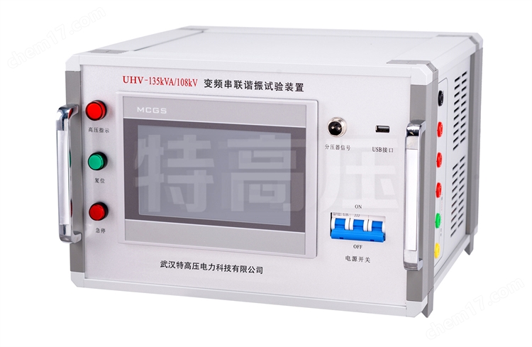
Variable Frequency Power Supply
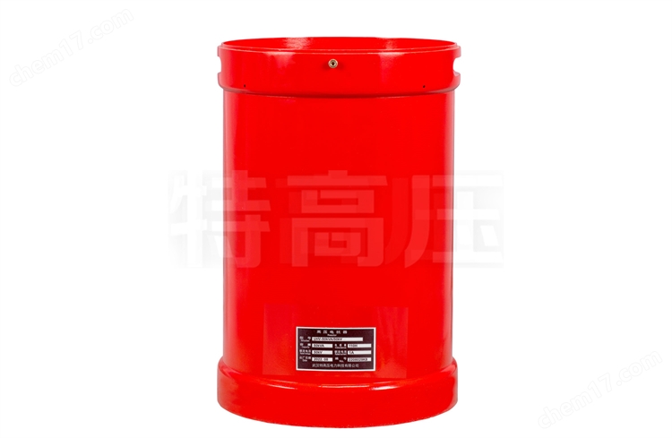
reactor

voltage divider

Voltage divider signal line

power cord

Reactor series parallel line

Reactor series parallel line
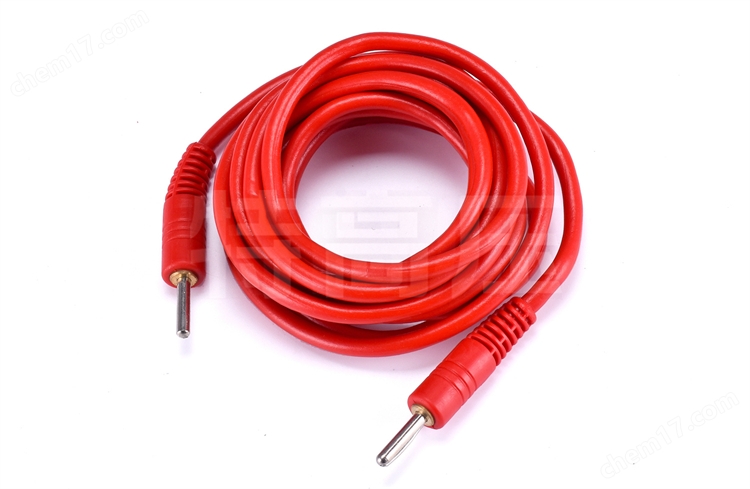
Variable frequency source output line

High voltage output line

Incentive variable output line

ground wire

Specialized testing line crocodile clip

Specialized testing line pliers

USB drive
Product detail images

Incentive Transformer

Incentive Transformer Panel

Excitation transformer input
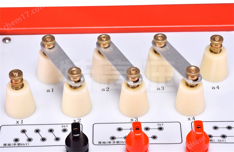
Excitation transformer terminal

Variable Frequency Power Supply

Variable frequency power supply display screen

Variable frequency power input

Variable frequency power supply grounding

Variable frequency power printer

Variable frequency power supply USB interface

Variable frequency power switch


