application application
|
|
|
|
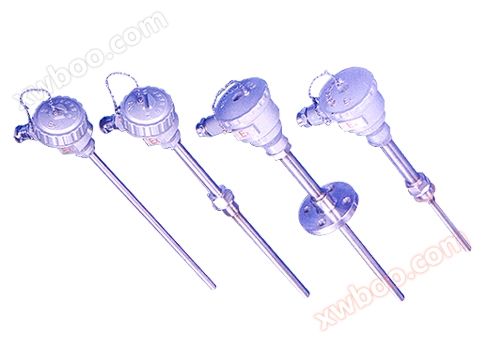
Usually used in conjunction with display instruments, recording instruments, etc. Directly measure the temperature of liquid, vapor, gas media, and solid surfaces within the range of 0-1300 ℃ in the presence of hydrocarbon explosions at the production site.
|

|
|
|
|
characteristic
|
● Multiple explosion-proof forms with good explosion-proof performance;
● Spring type temperature sensing element with good anti vibration performance;
● Large measurement range;
High mechanical strength and good pressure resistance.
|
|
|
|
Working principle
|
|
|
Explosion proof thermocoupleBy utilizing the principle of gap explosion-proof, design junction boxes and other components with sufficient strength, and seal all parts that can generate sparks, arcs, and dangerous temperatures inside the junction box cavity. When an explosion occurs inside the cavity, it can be extinguished and cooled through the gap between the joint surfaces, preventing the flame and temperature after the explosion from being transmitted outside the cavity, thus enabling temperature measurement.
|
|
|
|
|
Main technical parameters
|
|
● Product execution standards
IEC584
GB/T16839-1997
IEC1515
JB/T5518-91
GB3836
|
|
|
|
|
|
Room temperature insulation resistance
|
|
● Room temperature insulation resistance
The insulation resistance between the electrode and the outer sheath of the thermocouple is tested at an ambient temperature of 20 ± 15 ℃, relative humidity not exceeding 80%, and a test voltage of 500 ± 50V (DC)
≥ 100M Ω· m.
|
|
|
|
|
Temperature measurement range and allowable deviation
|
|
|
● Temperature measurement range and allowable deviation
|
|
|
model
|
Graduation
|
Allowable error and material grade
|
|
Level I
|
class ii
|
|
Allowable deviation
|
Temperature measurement range ℃
|
Allowable deviation
|
Temperature measurement range ℃
|
|
WRN
|
K
|
±1.5℃
±0.004│t│
|
-40~+375
375~1000
|
±2.5℃
±0.0075│t│
|
-40~+333
333~1200
|
|
WRM
|
N
|
±1.5℃
±0.004│t│
|
-40~+375
375~1000
|
±2.5℃
±0.0075│t│
|
-40~+333
333~1200
|
|
WRE
|
E
|
±1.5℃
±0.004│t│
|
-40~+375
375~800
|
±1.5℃
±0.004│t│
|
-40~+333
333~900
|
|
WRF
|
J
|
±1.5℃
±0.004│t│
|
-40~+375
375~750
|
±1.5℃
±0.004│t│
|
-40~+333
333~750
|
|
WRC
|
T
|
±1.5℃
±0.004│t│
|
-40-~+125
125~350
|
±1℃
±0.0075│t│
|
-40~+333
133~350
|
|
WRP
|
S
|
±1℃
±[1+0.003(t-1100)]
|
0~+1100
1100~1600
|
±2.5℃
±0.0025│t│
|
0~600
600~1600
|
|
|
● List of Evidence Collection
|
|
|
Explosion proof level
|
Explosion proof certificate number
|
certificate authority
|
|
dIIB T4
|
GYB96450
|
NEPSI
|
|
dIIB T4
|
GYB96453
|
NEPSI
|
|
dII CT5
|
GYB98339
|
NEPSI
|
|
dII CT5
|
GYB97197
|
NEPSI
|
|
iaIICT6
|
GYB99412
|
NEPSI
|
|
Note: NEPSI explosion-proof certification is a national level instrument explosion-proof safety supervision and inspection station.
|
|
Explosion proof grouping form
|
|
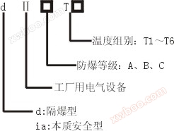
○ Electrical equipment category
Class I - Electrical equipment for underground coal mines
Class II - Electrical Equipment for Factory Use
○ Explosion proof rating
Explosion proof thermocoupleThe explosion-proof rating is divided into three levels: A, B, and C, based on the maximum safe clearance for use in explosive gas mixtures.
|
|
category
|
level
|
Maximum Test Safety Gap (MESG) mm
|
|
II
|
A
|
0.9≤MESG
|
|
B
|
0.5<MESG<0.9
|
|
C
|
MESG≤0.5
|
|
|
○ Temperature group
Explosion proof thermocoupleThe temperature group is divided into T1 to T6 according to the maximum allowable surface temperature of its exposed part.
|
|
Temperature group
|
Maximum allowable surface temperature ℃
|
|
T1
|
450
|
|
T2
|
300
|
|
T3
|
200
|
|
T4
|
135
|
|
T5
|
100
|
|
T6
|
85
|
|
Explosion proof level
EXdⅡ□T□
ExiaⅡ□T□
● Protection level: IP65
|
|
|
|
|
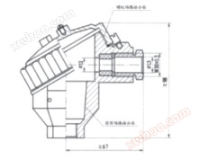
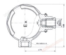
Form of junction box
|
|
|
D Ⅱ BT □ level
|
● D Ⅱ CT □ grade
|
|
|
|
|
|
Model naming method
|
|
|
W
|
Temperature instrument
|
|
|
|
|
|
|
|
|
|
|
|
|
|
|
|
|
|
|
|
|
|
|
|
|
|
|
|
|
|
|
|
|
|
|
|
|
|
|
|
|
|
|
|
|
|
|
|
|
|
|
R
|
thermocouple
|
|
|
|
|
|
|
|
|
|
|
|
|
|
|
|
|
|
|
|
|
|
|
|
|
|
|
|
|
|
|
|
|
|
|
|
|
|
|
|
|
|
|
|
|
|
|
|
|
|
Index number of temperature sensing element material
|
M
N
E
F
C
P
Q
R
|
Nickel chromium silicon nickel silicon N
Nickel chromium nickel silicon K
Nickel chromium copper nickel E
Iron Copper Nickel J
Copper Copper Nickel T
Platinum rhodium 10 platinum S
Platinum rhodium 13 platinum R
Platinum rhodium 30- Platinum 6B
|
|
|
|
|
|
|
|
|
|
|
|
|
|
|
|
|
|
|
|
|
|
|
|
|
|
|
|
|
|
|
|
|
|
|
|
Even number of threads
|
not have
2
|
Single tube
Double branch
|
|
|
|
|
|
|
|
|
|
|
|
|
|
|
|
|
|
|
|
|
|
|
|
|
|
|
|
|
|
|
|
|
|
Installation fixed form
|
1
2
4
5
|
No fixed device
Fixed thread
Flange
Flexible tube connector type
|
|
|
|
|
|
|
|
|
|
|
|
|
|
|
|
|
|
|
Form of junction box
|
|
4
|
explosion-proof type
|
|
|
|
|
|
|
|
|
|
|
|
|
|
|
|
|
|
|
Protection tube diameter
|
0
1
|
Φ16
Φ12(Φ20)
|
|
|
|
|
|
|
|
|
|
|
|
Workplace format
|
|
G
|
variable cross-section
|
|
|
|
|
|
|
|
|
|
|
|
|
W
|
R
|
N
|
2
|
——
|
2
|
4
|
0
|
G
|
Typical Model Example
|
|
|
|
|
|
Explosion proof thermocoupleSelection Notice
|
|
1) Model number
2) Dividing number
3) Explosion proof shield grade
4) Accuracy level
5) Installation fixed form
6) Material of protective tube
7) Length or insertion depth
Example AExplosion proof thermocouple, K-type, fixed thread M27 × 2, explosion-proof grade dIIBT4, protective tube 316L length 450mm, insertion depth 300mm.
WRN-240, K, L=450 × 300, M27 × 2, dIIBT4 protective tube 316L.
|