-
E-mail
940009794@qq.com
-
Phone
1395802750715968172475
-
Address
No. 159, Nanshan North Road, Renhe Street, Yuhang District, Hangzhou City
Product Categories
Hangzhou Weige Electronic Technology Co., Ltd

Electric Push Rod Testing System
NegotiableUpdate on 04/22
- Model
- Nature of the Manufacturer
- Producers
- Product Category
- Place of Origin
Overview
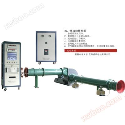
Host introduction: This project is mainly used to test linear electric motors. The full inspection items include pushing out the no-load test, pulling back the no-load test, pushing out the load (pushing) test, and pulling back the load
Product Details
Electric Push Rod Testing System
catalogue
Chapter 1Overall project introduction……………………………………………………… 5
1.1. Requirements Analysis
1.1.1 Characteristics and Industry Analysis of the Tested Motor Product 5
1.1.2 Scope of Supply for the Project 5
1.1.3 Project Purpose and Object of Use 5
1.1.4 On site environmental conditions
1.2. Overall Project Design (Scheme Implementation) 5
1.2.1 Project design ideas and concepts
1.2.2 Project Principle Block Diagram 6
1.2.3 Overview of Project Construction 6
1.2.4 Overall testing capability of the project (equipment accuracy range) 6
1.2.4 Project Reference Units and Definition Methods 6
1.2.5 Overall physical image (rendering) of the project 7
Chapter 2Introduction to project functions (layers)………………………………………………………… 8
2.1. Test items based on standards (standard codes)
2.2. List of Test Items (Reference Standards) 8
2.3. Detailed introduction of experimental items
2.3.1 No load Test 8
2.3.2 Load Test 8
2.3.3 Lock up Test 8
Chapter 3Introduction to the Electrical Measurement and Control Unit of the Project………………………………………………… 9
3.1 Overview 9
3.1.1 Design Basis Standards 9
3.1.2 Implementation of Electrical Measurement and Control Scheme 9
3.1.3 Electrical Measurement and Control Principle Block Diagram
3.2 Introduction to Electrical Measurement and Control Unit Modules (Main Configuration) 9
3.2.1 Measurement and Control Cabinet 10
3.2.1.1 Cabinet Unit 11
3.2.1.2 Measurement Unit 11
3.2.1.3 Electrical Control Unit 13
3.2.1.4 Information Supporting Unit 16
3.2.1.5 Power Supply Unit 17
3.2.1.6 Wire Unit 18
3.2.2 Electrical Transmission Unit 19
3.2.3 Power Supply Unit 20
3.2.4 Sensor Unit 20
Chapter FourIntroduction to the mechanical structural units of the project………………………………………………………… 23
4.1 Overview 20
4.1.1 Overall structural unit design ideas and concepts 23
4.1.2 Overview of Mechanical Structure Construction 23
4.1.3 Overall testing capability (process) of mechanical structure 23
4.2 Mechanical Structure Unit Module Configuration and Technical Requirements 24
4.2.1 Measurement and Control Cabinet 24
4.2.2 Dynamometer and Load 24
4.2.3 Testing Platform 24
4.2.4 Couplings 24
4.2.5 Fixtures 25
4.2.6 Safety Protection 26
4.2.7 Hardware Accessories 26
Chapter 5Software Unit Introduction…………………………………………………………… 27
5.1 Overview 27
5.1.1 Design Basis Standards 27
5.1.2 Analysis of Software Function Composition 27
5.1.3 Software Physical Image (Interface Image) 27
5.2 Software Unit Introduction 28
5.2.1 Communication Layer 28
5.2.2 Interface Layer 28
5.2.2.1 Startup Interface 28
5.2.2.2 Test Interface 28
5.2.2.3 Setting Interface 30
5.2.2.4 Report Interface 32
5.2.3 Software Database and Algorithms 34
5.2.4 Software Functions 34
5.2.4.1 Manual Testing 34
5.2.4.2 Automatic Testing 34
Chapter VI Technical process requirements for on-site integrated design (on-site layout)………………………………… 35
6.1 Overall Technical Requirements 35
6.1.1 On site integration design ideas and concepts 35
6.1.2 Overview of On site Integrated Design Construction 35
6.1.3 Overall testing process capability for on-site integrated design 36
Chapter 7Introduction to Project Homework Process Management…………………………………………………… 36
7.1 Project Requirements Process Control 36
7.1.1 Project Requirements Research and Control 36
7.1.2 Project Scope Definition 36
7.1.3 Project Requirement Change Control 36
7.1.4 Project Requirements Review and Control 36
7.2 Project R&D Process Control 36
7.2.1 Project Proposal Review 36
7.2.2 Design (Development) Review 36
7.3 Project Manufacturing Process Flow Control 36
7.3.1 Assembly Process Control 36
7.3.2 Debugging Process Control 36
7.3.3 Control of Test Process
7.3.4 Pre acceptance process control in the factory
7.3.5 Pre acceptance 37
7.3.6 Final Acceptance 37
7.3.7 Basis for Final Acceptance 37
7.3.8 Final Acceptance Criteria 37
7.3.9 Acceptance period
7.3.10 Shipping logistics and transportation control
7.4 Customer On site Process Control 38
7.4.1 Pre sales Scheduling Control............................................................... 38
7.4.2 On site unboxing control
7.4.3 On site installation control 38
7.4.4 On site debugging control
7.4.5 On site Test Control 38
7.4.6 On site acceptance control
7.4.7 On site Training Control 38
7.5 Main Material Development and Procurement (Supply Chain) Process Control
7.5.1 Supplier Control 38
Chapter One Overall project introduction
1.1requirement analysis
1.1.1Characteristics and Industry Analysis of the Tested Motor Product
This testing equipment is used for online detection of performance parameters of linear electric motors, detection and qualification judgment, data storage, analysis, printing, automatic alarm for abnormal and unqualified situations, etc. Suitable for performance testing of electric push rod motors, it can improve the production testing efficiency of electric push rod motors and replace traditional pointer instruments
1.1.2Scope of project supply
1.1.3Project purpose and target audience
This project is mainly used to test linear electric motors. The full inspection items include no-load test, no-load test, load (push) test, load (push) test, load (pull) test, load (pull) test, static push test, static pull test, etc.
1.1.4On site environmental conditions
1. Environmental temperature: -10 to+45 ℃
2. Relative humidity: ≤ 90%
3. Altitude: ≤ 1000m
4. Location of use: Indoor
5. Power supply voltage: AC 380 ± 10% V 50 ± 1Hz
6. Grounding requirement: There must be an independent grounding wire (impedance ≤ 4 Ω)
7. Power supply system connection: manually operated disconnect device
8. Stay away from electromagnetic interference and mechanical vibration sources on site
9. There shall be no excessive dust, acid, alkali, salt, corrosive or explosive gases in the air
1.1.5Quality requirements for power grid
1. The range of AC voltage variation is equal to ± 10% of the rated input voltage, for a short period of time (not exceeding 0.5s)
The fluctuation range of AC voltage is -15% to+10% of the rated input voltage
2. The peak value of non repetitive transient voltage should be ULSM ≤ 2.5 times the peak value of operating voltage ULWM
3. The peak value of the repeated transient voltage should be ULRM ≤ 1.5 times the peak value of the operating voltage ULWM
4. The deviation of power frequency should not exceed ± 2% of the rated frequency, and the relative harmonic component should not exceed 10%.
1.2 Overall project design (scheme implementation)
1.2.1Project design ideas and concepts
Principle for selecting experimental equipment: It can fully meet the configuration requirements of the test bench proposed by Party A
Principle of maturity and reliability: The design of the test bench first ensures maturity and reliability, selecting mature technology and equipment:
The system design is mainly based on the principles of easy installation, debugging, and maintenance:
Design principles: standardization, serialization, generalization, integration, progressiveness, safety:
Appearance requirements: The surface of the control cabinet should be treated with spray coating, taking into account heat dissipation, cleanliness and aesthetics, and clear labeling
The system software is linked to barcode or QR code scanning and product testing data The system consists of single-phase reactors, three-phase reactors, single-phase transformers, and three-phase transformer testing interfaces, and the test data is automatically saved and exported to PC devices
1.2.2Project principle framework
1.2.3Overview of Project Construction
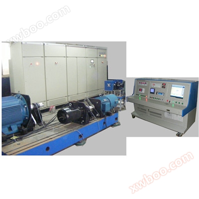
The experimental system consists of a measurement and control cabinet, sensor unit, electrical transmission unit, DC stabilized power supply, etc.
1.2.4Overall testing capability of the project (equipment accuracy range)
This system uses an industrial computer specifically designed for automatic testing of electric push rod motors. It has the characteristics of fast testing speed, high accuracy, easy use, and good reliability, making it a specialized comprehensive testing equipment for electric push rod motors at the factory
1.2.4Project reference units and definition methods
1.2.5Overall physical image of the project (rendering)
Chapter One Introduction to project functions (layers)
2.1 Experimental project based on standard (standard code)
1. GB/T 755-2008 "Rating and Performance Test Methods for Rotating Electrical Machines"
2.2.List of Experimental Projects (Reference Standards)
|
Test project name
|
|
1.no-load test
|
|
2.load test
|
|
3.locked rotor test
|
2.3 Detailed introduction of experimental projects
2.3.1no-load test
1.Launch no-load testing:Test without load, test the voltage, current, input power, power factor, linear velocity, and displacement of the electric push rod motor.
2.Pull back empty load test:Test without load, test the voltage, current, input power, power factor, linear velocity, and displacement of the electric push rod motor.
2.3.2load test
1.Launch load (push) testing:Test the load, test the voltage, current, input power, power factor, thrust, linear velocity, and output power of the electric push rod motor
2.Pull back load (push) test:Test the load, test the voltage, current, input power, power factor, tension, linear velocity, and output power of the electric push rod motor
3.Launch load (pull) testing:Test the load, test the voltage, current, input power, power factor, thrust, linear velocity, and output power of the electric push rod motor
4.Pull back load test:Test the load, test the voltage, current, input power, power factor, tension, linear velocity, and output power of the electric push rod motor
2.3.3locked rotor test
1.Static push test:Test the motor being tested for locked rotor, test the voltage, current, input power, power factor, thrust, and displacement of the electric push rod motor.
2.Static tensile test:Test the motor being tested for locked rotor, test the voltage, current, input power, power factor, tension, and displacement of the electric push rod motor.
Chapter 2 Introduction to the Electrical Measurement and Control Unit of the Project
3.1 overview
3.1.1Design Basis Standards
1. The electrical system shall be inspected and accepted in accordance with GB5226-85.
2. The interference and anti-interference ability of the electrical system comply with the requirements of ECE regulations.
3.1.2Implementation of Electrical Measurement and Control Scheme
The measurement control cabinet mainly includes a measurement unit responsible for data acquisition, an electrical PLC controlling relay switching, an information supporting system including a computer host, keyboard and mouse, and a power supply unit including a 500W variable frequency power supply with RS232 communication, which can achieve voltage programmable adjustment.
The sensor unit includes a grating ruler and tension and compression sensors responsible for distance measurement, as well as thrust and tension detection and transmitting signals to the PLC and signal conversion module of the electrical unit.
The electrical transmission unit includes a servo controller, servo motor, and planetary gearbox, responsible for testing and loading control.
The power cabinet includes a DCS5030 DC regulated power supply, with an output voltage of 0-50V that can be programmed and adjusted.
Measurable parameters: including motor operating voltage, current, and input power; Motor push/pull load, linear velocity, output power, motor stroke, self-locking force testing, etc.
3.1.3Physical composition analysis
1. Industrial control computer: including host, 17 "LCD display, mouse, keyboard, etc
2. Two sets of 50V30A external voltage feedback DC stabilized linear power supply and 500W variable frequency power supply
3. One deceleration servo electric dynamometer
4. One DC parameter meter
5. One standard industrial control cabinet
6. One workbench with a maximum thrust of 1000N and a maximum stroke of 500mm
7. A set of motor start stop push (pull) motion control testing system
8. One load sensor (1000N)
9. Guangshan ruler speedometer, one
3.2 Introduction to Electrical Measurement and Control Unit Module (Main Configuration)
3.2.1Measurement and control cabinet
1.Design ideas and concepts:
(1) Measurement testing
Realize the collection, analysis, processing, display, printing of test reports, data storage, and partial control functions of experimental data through computer software. The entire testing system consists of an industrial computer, hardware for data acquisition and measurement instruments, measurement software, and other components.
(2). The design principle is reliability, safety, economy, practicality, operability, maintainability, and progressiveness.
(3). The measurement and control system of the testing equipment adopts industrial control computer+PLC control+digital display measuring instrument.
(4). The cabinet and box surfaces of the experimental system are sprayed with plastic, and all markings are clear and not easily detached.
(5). All equipment and installation materials in this testing device are brand new, and the measurement units of the equipment's parts, instruments, and all drawing data are all based on the International Single (SI) standard.
2.Physical composition:The measurement control cabinet system (1 set) is divided into cabinet body, measurement unit, electrical control unit, information matching unit, and power supply unit. The entire operation is divided into manual (panel button)/automatic (program control) operation.
3.Functional features:
1. Measurement method: A microcomputer measurement circuit is used to configure an electrical parameter measuring instrument, a grating ruler, and a tension compression sensor. The intermediate link uses a signal conditioning interface module, and the signal acquisition and measurement tasks are completed by the electrical parameter tester and sensor unit+computer.
2. Control method: Directly controlled by PLC, with stable system performance and good system scalability.
3. Test data processing: The test results are saved on the microcomputer test bench of the industrial control computer equipped with Xunyan Technology's original industrial computer. The test result data is directly saved on the hard drive of the industrial control computer. The manually measured data is manually input into the test software interface and then saved in the memory, providing local database function for local query and access of test data. The software is designed with automatic generation of test reports and provides output function.
4. The experimental system includes an operating cabinet, industrial computing (including keyboard and mouse), 17 inch industrial LCD display, panel display instruments and various indicator lights, control switches and buttons;
5. The experimental system integrates computer interface and acquisition modules, automatic control modules, related protection modules, data acquisition modules, etc.
6. This system has the capability to test electric push rod models: the customer provides a prototype. The motor detection requires easy installation and disassembly. During installation and disassembly, a switch is used to control the stroke, ensuring that the motor installation hole can be quickly installed and removed.
7. Pass testing project: Pass testing involves testing the linear speed, load, voltage, current, power, stroke, self-locking force, etc. in both push and pull directions.
8. Testing method: There are two types of testing methods: point testing and curve testing (both can be tested). Users can choose either option according to their own requirements during the testing process.
The so-called point testing method refers to testing the three operating points of the motor, namely the no-load point, the load point, and the locked rotor point. The torque value of the load point and the testing time for each point (i.e. the maintenance time of the motor operating point) can be set arbitrarily. The test result data can be the average or the final test value (optional for users).
The curve testing method is to test the T-n curve of the motor, and then the user sets the load point torque value based on the length of time the electric rod runs, and calculates the parameters of the no-load point, load point, and stall point on the curve. The processing of parameters can be done after curve fitting or without fitting (optional). We recommend that users choose the point testing method when conducting online testing, as it is more in line with the actual working conditions of the motor and can avoid testing errors caused by the rotational inertia of the motor and magnetic powder brake under the curve testing method.
4.Main List Configuration:
|
Serial Number
|
Equipment name
|
brand
|
sketch
|
|
1
|
cabinet
|
Weig
|
Vertical cabinet, capable of manual and automatic operation of the entire system
|
|
2
|
GDW1206A DC parameter measuring instrument
|
Weig
|
1 unit, measuring the voltage, current, and power of the electric push rod DC motor, with a voltage range of 0-300V and a current range of 0.03-50A, with an accuracy level of 0.5
|
|
3
|
GDW1200C AC parameter measuring instrument
|
Weig
|
1 set, electric push rod AC motor voltage, current, power, voltage 0-300V, current 0.03-20A, accuracy level 0.5
|
|
4
|
Variable frequency power supply
|
Weig
|
1 output 110V: 4.6A, 220V: 2.3A Power: 500W
|
|
5
|
PLC, Signal conversion module
|
Mitsubishi
|
a set
|
|
6
|
Industrial computer, monitor, printer, scanning gun
|
Xunyan Industrial Control
|
Data processing, collection, control, and report curve printing
|
5.Effect diagram of measurement and control cabinet
3.2.1.1cabinet
1. Cabinet operation: The entire cabinet can be manually and automatically operated
3.2.1.2Measurement unit
1.DC parameter tester
1.Design ideas and concepts
GDW1206A digital electrical parameter tester is an intelligent instrument that uses digital sampling technology to analyze and process signals. Accurately measure the effective values of parameters such as voltage, current, and power of DC electrical equipment. Its working process is as follows:
1.Convert the measured signal into an electrical signal of appropriate amplitude;
2.Divide this signal into discrete signals at a frequency much higher than the measured signal;
3.Using high-speed AD converters to convert discrete signals into digital quantities;
4.Using microprocessors to calculate the collected digital data;
5.Display the final calculation result in numerical form, with positive and negative values depending on the connection method.
2.Functional composition and analysis
The measured signal value is the true effective value;
Direct digital display can reduce human reading errors;
The same applies to signals with waveform distortion;
One instrument can measure multiple parameters;
Easy to achieve intelligence and can be connected to computers.
The digital electrical parameter tester can be widely used for product testing and measurement by manufacturers and departments in industries such as motors and pumps. With 232 communication function, it can be easily connected to computers for networking.
3. TECHNICAL INDEX
|
Measurement parameters
|
measuring range
|
measurement error
|
Resolution
|
Overload capacity
|
|
Voltage (DC)
|
(0.80~300.0)V
|
± (0.4% reading+0.1% range)
|
0.01V
|
±320V
|
|
Current (DC)
|
(0.050~50.00)A
|
<10A 0.001A
≥10A 0.01A
≥100A 0.1A
≥1000A 1A
|
±52.5A
|
|
|
75mV
|
1.05 times
|
|||
|
power
|
U*I
|
|
<1000W 0.1W
≥1000W 1W
≥2kW 10W
|
|
4.Front panel rendering
2.AC parameter measuring instrument
1.Design ideas and concepts
The GDW1200C digital electrical parameter measuring instrument is an intelligent instrument that uses digital sampling technology to analyze and process signals. The measurement signal is a 5Hz~1kHz AC power frequency signal. Its working process is as follows:
1.Convert the measured signal into an electrical signal of appropriate amplitude;
2.Divide this signal into discrete signals at a frequency much higher than the measured signal;
3.Using high-speed AD converters to convert discrete signals into digital quantities;
4.Using microprocessors to calculate the collected digital data;
5.Display the final calculated result in numerical form.
2.Functional composition and analysis
The measured signal value is the true effective value;
Direct digital display can reduce human reading errors;
The same applies to signals with waveform distortion;
One instrument can measure multiple parameters;
Easy to achieve intelligence and can be connected to computers.
Digital electrical parameter measuring instruments can be widely used for testing household appliances, motors, lighting equipment, and other products, as well as for testing equipment in metrology departments. With 232 communication function, it can be easily connected to computers for networking.
3.TECHNICAL INDEX
Table 1 Main Performance and Technical Indicators of Instruments
|
parameter
|
measuring range
|
measurement error
|
Resolution
|
notes
|
|
voltage
|
(10~300)V
|
± (0.25% reading+0.25% range)
|
0.1V
|
Allow overload of 1.2 times the range
|
|
electric current
|
(0.02~20) A
|
0.001A
|
Allow overload of 1.2 times the range
|
|
|
power
|
U*I*PF
|
PF=1.0: ± (0.25% reading+0.25% range)
PF=0.5: ± (0.5% reading+0.5% range)
|
0.1W
|
|
|
Power factor
|
0.2~1.0
|
±0.02
|
0.001
|
|
|
frequency
|
5Hz~1kHz
|
±0.2 Hz
|
0.1Hz
|
|
4.Front panel rendering
3.2.1.3Electrical control unit
1.Functional composition analysis
1.Communication relay module
Electrical switching is controlled by AC contactors, which have stable and reliable performance and fast switching
2.PLCAnd signal conversion module
Using Mitsubishi PLC to control the relay part commands and AC contactor switching, the design concept of relay switching program control and hardware interlock ensures the reliability of electrical switching
The distance signal output by the grating ruler is sent to the PLC for collection and converted into a digital signal.
Analog extended output module, responsible for analog-to-digital conversion control of DC stabilized power supply output to test voltage, etc.
The Analog Extended Input/Output Module (Panasonic) is responsible for amplifying the weak signal of the tension and compression sensor and transmitting the output signal to the PLC for data acquisition.
3.autotransformer
The three-phase self coupling transformer provides stable power supply for the servo controller
4control panel
1. Include a "power" switch to control the on/off of the power supply. Emergency stop button; Disconnect the power supply in case of emergency.
2. Test/Stop control button for the tested motor;
3. Control the forward and reverse rotation of DC motors
2.TECHNICAL INDEX
Analog Extended Input/Output Module: A2P (Input Power DC24V, Output 0-10V/4-20mA): Error ± 0.5% Torque Measurement Range 10N~10000N 1 unit
3.Physical photos
3.2.1.4Information supporting unit
1.Design ideas and concepts
Industrial grade computer, 2G memory, 500g hard drive, DVD drive, USB interface, 17 "Lenovo LCD display laser printer, testing software compatible with the system, software combined with the computer for data acquisition and processing
2.Physical composition and analysis
The information supporting unit includes an industrial computer, a monitor, and a printer. Mainly used for data transmission speed and display, printing data reports
3.TECHNICAL INDEX
1. Network card 1000/100/10 MByte
2. USB keyboard
3. USB Mouse
4. Printer: Black and white laser A4
5. Scanning gun
4.Physical photos
3.2.1.5POWER
1.Design ideas and concepts
The VG series single-phase program-controlled variable frequency power supply is designed based on the technical conditions of SJ/T10541 and GB/T7260, with a 16 bit microcontroller as the core and electronic power devices as the power output unit. It adopts new technologies and modular structures such as digital frequency division, phase locking, waveform instantaneous value feedback, pulse width modulation, IGBT output, etc. It has strong load adaptability, good output waveform quality, easy operation, small size, and light weight, and can be widely used in laboratories, testing lines, and production lines that need to simulate various power environments and special requirements.
2.Functional composition and analysis
The schematic diagram is as follows:
Input rectification, voltage stabilization, IGBT inverter
Drive voltage transformation and output filtering
Waveform synthesis waveform control detection
Given f
U given
Keyboard display voltage control effective value output
3.TECHNICAL INDEX
1. Input
Single phase: 220V ± 10% 50Hz
Three phase four wire: 380V ± 10% 50HZ
2. Output
Single phase: 1~300V ± 1% (110V: 4.6A, 220V: 2.3A, power: 500W)
Output waveform: sine wave
Waveform distortion: ≤ 2% (resistive load)
Output frequency: 47~63HZ ± 0.01%
Source voltage effect: ≤ 2%
Load effect: ≤ 2%
Overload capacity: greater than 120% (15S alarm)
Greater than 150% (5S alarm)
Suitable for loads: resistive, rectifier, and inductive loads (for rectifier and inductive loads, derating is required)
3. Efficiency: greater than 80%
4. Protection function: Output short circuit, overload, over temperature protection
4.Physical photos
3.2.1.6Wire unit
The wire unit mainly includes one set of power inlet, testing wire, fixtures, etc
3.2.2Electrical transmission unit
1.Design ideas and concepts
The electrical transmission unit mainly includes Panasonic servo controller, Panasonic servo motor, and planetary reducer Mainly used for controlling motor loading and load testing control
2.Physical composition and analysis
1 Panasonic servo controller
1 planetary gearbox
1 Panasonic servo motor
3.Functional and technical indicators and analysis
planetary reducer:PX142-12:1/M (input end is Panasonic MGME302GGG servo motor) Xupu transmission rated output torque 950N. m Reduction ratio: 12:1
Panasonic servo motor: MGME302GGG-3kW (rated 28.7N. m, 1000r/min)
4.rendering
Panasonic servo controller
Planetary gearbox
3.2.3POWER
1.Design ideas and concepts
The DCS series DC stabilized and current stabilized power supply is a type of stabilized and current stabilized power supply that is pre stabilized by thyristors and adjusted in series. The output voltage is continuously adjustable, and it automatically converts high-precision DC power supply with stable voltage and current. The output voltage of the circuit can be adjusted from 0V, and can be selected arbitrarily within the rated range. The overvoltage protection point can also be selected arbitrarily. In the steady current state, the steady current output current can be adjusted within the rated range.
This instrument can be widely used for DC motor detection, debugging, aging, production, factories, schools, research institutes, and various departments of the national economy.
2.Functional characteristics and analysis
In order to improve the reliability and user safety of the power supply, as well as the short-circuit protection function, a load short circuit occurs when the power supply is operating in a stable current state and the voltage output is below 2V, with the output current being the set stable current value.
3.Functional and technical indicators and analysis
1. Output voltage: 50V Accuracy: 2%
2. Output current: 30A Accuracy: 2%
3. Power effect: 5 ‰
4. Load effect: 5 ‰
5. Periodic and random drift voltage: ≤ 200mV
6. Power supply: AC220V ± 22V, 50Hz ± 2Hz (system working power supply)
7. Usage conditions: Environmental temperature (0~40)oC Relative humidity ≤ 90% R
4.Physical photos
3.2.4Sensor Unit
1.Design ideas and concepts
The tension and compression sensor is used to test the push-pull force of the motor, and the grating ruler is used to test the displacement and linear velocity of the linear motor
3.List configuration
1 tension and compression sensor
1 set of grating ruler
4.Installation diagram for grating ruler
Micro switch model and appearance: LXW-AZ7312 Xinling Industrial Control
5.TECHNICAL INDEX
1.Tension and compression sensor:101BS-1000kg (Yongzheng)
2.Grating ruler:550mm resolution: 5 μ m output signal: 5V TTL square wave, differential output (long line drive), 24V HTL square wave, 24V NPN collector open circuit operating temperature: 0-40 ° C
6.Physical photos
Tension and compression sensor
Grating ruler
Chapter One Introduction to the mechanical structural units of the project
4.1Overall technical requirements
4.1.1Design ideas and concepts for overall structural units
1. The equipment shall be painted according to the color palette provided by the factory, and the color tone of the equipment shall be consistent.
2. In order to facilitate maintenance and upkeep of the equipment, the safety cover that is frequently opened and closed can be easily removed.
3. The height, control panel height, and display screen height are designed ergonomically.
4. Uniform appearance standards and consistent style
4.1.2Overview of Mechanical Structure Construction
The mechanical structure mainly includes measurement and control cabinets, dynamometers and loads, testing platforms, couplings, fixtures, safety protection, hardware accessories, etc
4.1.3Mechanical structure overall testing capability (process)
Various electrical modules are placed inside the cabinet, while electronic measurement modules use a chassis and are placed inside the cabinet. The module involved is designed in a closed manner.
4.2Mechanical structural unit module configuration and technical requirements
4.2.1Measurement and control cabinet
1.Physical composition and analysis
1. Cabinet: 19 inch ICT sleeper cabinet. The main skeleton is made of aluminum profiles and sheet metal, and the surface of the cabinet is sprayed with plastic. Integrated installation of electrical parameter meter, acquisition module, industrial computer, keyboard drawer, etc. inside the cabinet.
2. Panels: nameplate panel, instrument panel, control panel, blind panel, etc.
3. Electrical partitions: 2 electrical partitions, servo drives, contactors, etc.
2.Effect diagram of measurement and control cabinet
4.2.2Dynamometer and load
1Design ideas and concepts
Using servo drivers to control servo motors and gearboxes.
4.2.3test platform
1Design ideas and concepts
Iron plate 2169 * 1000 * 30mm
4.2.4coupling
1.Physical photos
4.2.5Fixture
1.Physical composition analysis
Servo motor fixed base, gear rack, guide rail slider, bracket, etc.
2.rendering
3.Rack and pinionPhysical photos
4.2.6safety protection
Glass cover.
4.2.7Hardware accessories
Screws, nuts, etc.
Chapter 2 Software Unit Introduction
5.1 overview
5.1.1Design ideas and concepts (algorithms and core technologies)
The system provides two sets of operation functions: manual and automatic.
2. The experimental system is constructed using industrial computers, with mature and reliable software and a Chinese interface for operation.
3. It has password permission protection.
4. The experimental software interface has exclusivity, and testers cannot access other application software interfaces
5. The user interface is user-friendly, easy to operate, and has manual, automatic, fixed-point, and durability testing methods, which means that the load can be manually, automatically, and fixed-point adjusted. The test data can be displayed on both instruments and computers, automatically generating test reports, conducting qualification judgments, and automatically protecting test results.
6. Have relevant prompt areas (operation instructions, error prompts, etc.)
7. Display area with relevant curves
8. Display area with information such as current operator name, time, tested product model and number
5.1.2Functional composition and analysis
1. It can automatically control the test motor to collect test data, perform data processing and parameter calculation, and generate and print test reports
2. The measurement data is automatically synchronized and recorded by the computer, ensuring the simultaneity of the test data, eliminating errors caused by manual reading of the meter, and greatly improving the efficiency of the experiment
3. High measurement accuracy and good repeatability
The motor number consists of model+year (2 digits)+month (2 digits)+day (2 digits)+serial number (4 digits). In automatic mode, simply connect the tested product as required, click start, and the experiment will be automatically completed The motor model can be freely added or deleted, which means that countless types of motors can be tested on the system as long as the torque is appropriate.
5. The unique automatic recording function of experimental data, which means that the software automatically records the test results when the test conditions are met, avoids the problem of difficulty in reading data due to unstable voltage during the test, and greatly shortens the time for obtaining data.
6. Standardize the testing process to avoid artificially changing the testing requirements
The 7 test software automatically converts the test results into standard data, which is beneficial for comparing the test results
The various parameters and test result data of the 8 motors are saved in the test server database in Excel format
The test software automatically determines whether the test results are qualified based on the motor reference data.
The 10 test results are automatically saved, and the test data for unqualified motors can be selected to be saved or not saved.
The layout format of the test report can be freely prepared and modified by relevant technical personnel
12. High degree of automation, saving time and manpower, greatly improving experimental efficiency, and reducing labor intensity
13 has operation guidance prompts and multiple protection functions (especially anti misoperation function)
14 is equipped with a USB interface, making it easy to transfer test reports and data to mobile storage media or connect to a printer
15 Check Xuan: You can search for the test data of each initial motor by motor model and number, and print it after completion.
16 Statistics: The qualification rate, unqualified parameter ratio histogram, pie chart, etc. of the initial test motor can be calculated by day, month, quarter, etc., and the results can be printed. (Easy to control product quality)
5.1.3Software physical image (interface diagram)
5.2 Software Unit Introduction
5.2.1 Communication layer
5.2.2 Interface Layer
5.2.2.1 Startup interface
5.2.2.2Test interface
1.Design ideas and concepts (algorithms and core technologies)
1. Data measurement: Data measurement mainly completes the measurement of various parameters. According to the difference in measurement methods and purposes, it is divided into measurements related to control parameters such as no-load, load, and locked rotor, as well as measurements of other general parameters. These data measurements are carried out using specialized equipment/instruments, and then exchanged and integrated into the system through communication.
2. Data processing: Data processing is an essential function of measurement and control systems. It organically combines independent and unrelated parameters to form a complete system, transforming unrelated data into interrelated and influential data.
3 Alarm: When the measured parameters reach the alarm value, the system prompts the user through methods such as lighting and font color reversal that the system has entered an alarm state. The alarm parameters include the qualification of the load current, load speed, and load torque in both directions of the motor, and provide audible and visual alarms.
1. Data display: The system provides three ways to display the measured data and the trend of data changes. Each dynamic measurement data is displayed in numerical form, real-time curves are used to reflect the recent changes in real-time data, and historical curves are used to reflect the trend of static data changes at various levels in the past
5. Individual testing refers to testing a single motor by setting the motor power supply to a constant voltage working state, where the voltage is constant.
6. During testing, opening and restoring can be used as one testing cycle for multi cycle testing, and the qualification of any cycle test result can be judged. The interface displays the test process status values, test results, and current and push-pull force curves.
2.Functional composition analysis
1. Empty load: divided into push/pull empty load test; Record a set of data, including voltage, current, input power, line speed, etc.
2. Load: divided into push out load (push), pull back load (push), pull out load (pull), pull back load (pull) testing; Record a set of data, including voltage, current, input power, push-pull force, linear velocity, output power, efficiency, etc.
3. Blockage: divided into static pushing and static pulling tests; Record a set of data, including voltage, current, input power, push-pull force, displacement, etc.
3.rendering
No-Load Test
Load Testing
lock rotor test
5.2.2.3Settings interface
1.Design ideas and concepts
1. Experimental process and condition parameter setting: The experimental process and condition parameter setting are to achieve the automatic control function of the system. A set of experimental process data is manually set in advance, and the system will automatically complete a complete experiment based on this set of experimental process data. If no abnormal situations occur during this experiment, no manual intervention is required.
2. Management of measurement parameters: The management of measurement parameters mainly completes the setting of measurement parameters, including the number of measurement parameters, the name, unit, range, etc. of each measurement parameter.
4. Management of alarm parameters: mainly set which parameters need to be alarmed, as well as the alarm value and protection value of each alarm parameter, and what the corresponding action is.
2.Functional composition and analysis
The upper and lower limits of alarm conditions and monitoring parameters can be freely set. When an abnormality occurs, the system displays the corresponding fault mode on the computer interface and can be linked according to the pre-set settings, including displaying messages, sound and light alarms, emergency stops, etc
3Parameter setting interface
3.1 Empty load parameter setting
3.2Load parameter setting
3.3Locking parameter setting
5.2.2.4Report interface
1.Design ideas and concepts
1. It has data evaluation function, which can easily display and analyze measurement data
2. The software system has the function of automatic data storage
3. The software system automatically generates test record files and important event record files during the test
2.Report interface rendering
Data query interface
Data statistics result interface
5.2.3database
1.Design ideas and concepts
1. Data storage: System data (system setting parameter data and measurement data) will be stored in the form of a database. In order to reduce system maintenance and usage costs, as well as meet the usage habits of most people, the system will use Microsoft EXCEL as the database
2. Data Conversion: The system also provides a data conversion tool that can convert data files saved in the database into Excel files
3. Data retrieval: The system provides a comprehensive logging function, which can fully record and reflect the environmental conditions at the time of the experiment
5.2.4.Functional composition and analysis
1. The software system has both local experimental database management system and network database management functions.
2. Software functions
5.2.4.1 Manual testing
5.2.4.2 Automatic testing
Chapter VI Technical process requirements for on-site integrated design (on-site layout)
6.1Overall technical requirements
6.1.1On site integration design ideas and concepts
Items that meet the common requirements of national standards and specifications related to the construction of test stations and factories, including but not limited to the contents listed in this article:
·Electrical performance;
·Mechanical and structural performance;
·Environmental adaptability performance;
·Radio interference and electrical interference;
·Magnetic field influence;
·Reliability and safety;
·Noise
·Other performance related requirements
6.1.2Overview of on-site integrated design and construction
The on-site integration adopts a measurement and control cabinet placed adjacent to a DC stabilized power supply
6.1.3On site integrated design overall testing (process) capability
Site Layout
Chapter 7 Introduction to Project Homework Process Management
7.1 Project requirement process control
7.1.1 Project Requirement Research and Control
7.1.2 Project Scope Definition
7.1.3 Project requirement change control
7.1.4 Project Requirements Review and Control
7.2 Project development process control
7.2.1 Project Proposal Review
7.2.2 Design (Development) Review
7.3 Project manufacturing process flow control
7.3.1 Assembly process control
7.3.2Debugging process control
1. The supplier is responsible for the installation and commissioning of the equipment at the user's location, and is fully responsible for the correctness of the equipment installation and commissioning.
Before installing and debugging the equipment, the supplier must sign a safety agreement with the user, and the supplier is responsible for the safety work of installation and debugging.
3. The supplier is fully responsible for lifting the equipment into place according to the lifting conditions at the installation site; When the installation of equipment exceeds the lifting equipment installed on site in the workshop, the supplier is responsible for renting a crane to lift the equipment and tools.
4. The supplier is responsible for connecting the equipment to water, electricity, oil, and gas pipelines.
5. The supplier is responsible for the installation, debugging, acceptance, and trial operation of the equipment. The special tools and testing instruments required during the debugging process shall be provided by the supplier.
6. The expenses incurred by the supplier's personnel during installation and commissioning shall be borne by the supplier.
7. If the installation and debugging personnel of the supplier are incompetent during the installation process, the user has the right to request a replacement of the installation personnel.
8. Any equipment damage or non-conforming components that occur during the installation process shall be promptly replaced and updated by the supplier free of charge.
9. The user shall provide the required public power (electricity, water, compressed air) according to the layout plan requirements.
7.3.3Experimental process control
7.3.4Pre acceptance process control in the factory
The equipment acceptance supplier shall provide the user with the confirmed equipment acceptance methods, steps, tools used, and standards adopted by both parties, as well as provide proof of the legality of the software involved and used in the equipment.
Equipment acceptance is divided into two steps: pre acceptance and final acceptance. Pre acceptance is conducted at the supplier's site, while final acceptance is conducted at the user's site.
The pre acceptance of the equipment is carried out at the supplier's site. One month before the equipment is shipped, the supplier invites two relevant personnel from the user to go to the supplier for equipment pre acceptance. Conduct pre acceptance of the basic parameters and performance of the equipment item by item according to the content specified in the technical agreement.
During the pre acceptance period of the equipment, the supplier must provide necessary support to the user. The costs incurred during pre acceptance shall be borne by the supplier, including insurance, travel expenses, and accommodation fees for the user's staff to visit the supplier's premises.
The acceptance content shall at least include:
1. Equipment appearance inspection, functional component configuration, and safety measures.
2. Power on the equipment and check all operating parameters to ensure there are no abnormal noises, electrical leaks, water leaks, or air leaks.
3. Review of equipment documents, including calibration certificates.
4. Check the consistency between the equipment and technical documents.
7.3.5Pre acceptance
After all project inspections and tests are completed and qualified, a pre acceptance report shall be written and signed by both parties. All projects, including those that cannot be pre accepted and those that pass pre acceptance, will be re inspected and confirmed during final acceptance, and the final acceptance shall prevail.
7.3.6Final acceptance
The final acceptance of the equipment is carried out at the user's site. The final acceptance of the test bench and its ancillary equipment shall be carried out at the user's site. After the installation and commissioning of the bench, it shall be loaded and continuously operated for 24 hours without any faults, and then handed over to the user for trial operation. After that, the final acceptance shall be carried out according to the technical agreement.
The technical liaison, installation, debugging, and training during the final acceptance period are the responsibility of the supplier, with the cooperation of the user.
7.3.7Basis for final acceptance
1) The operation status of the equipment.
2) Supplier's equipment factory inspection standards and relevant international standards.
3) The contract, technical agreement, design confirmation memorandum, and other technical documents recognized by both parties.
4) The quality certification documents provided by the supplier along with the equipment, the legal certificates of the software used, and the factory inspection records of the equipment.
7.3.8Final acceptance criteria
1) The scope of supply shall be consistent with the contract and technical agreement.
2) All devices shall be tested item by item according to the technical agreement to verify that they meet the requirements of the technical agreement.
3) The equipment provided by the supplier shall meet all the terms and requirements of the technical agreement and contract.
4) The final acceptance training effect inspection is qualified. After all project inspections and tests are completed, a final acceptance report shall be written, signed and confirmed by representatives of both parties, and the warranty period shall begin.
7.3.9Acceptance deadline
The equipment shall arrive at the user's site within 4 months from the effective date of signing the test bench contract, and all goods shall be delivered (subject to the delivery date specified in the contract or the actual delivery date). Installation and commissioning shall be completed within 1 month to meet the quality requirements stipulated in the contract.
1. Loading and unloading requirements
2. Installation environment requirements
3. Third party testing report (inspection report), factory certificate of conformity
7.3.10.Shipping logistics and transportation control
The supplied goods must be packaged securely and transported in sturdy wooden boxes. Measures such as moisture-proof, moisture-proof, rainproof, shockproof, and rust proof should be taken according to the different shapes and characteristics of the goods, so that they can withstand multiple handling, loading and unloading, and long-distance transportation, to ensure that the goods can be safely transported to the destination specified in the contract without damage or erosion. Suppliers shall be responsible for rust, damage, and injury caused by improper packaging. If the weight of the goods packaging reaches or exceeds 2 tons, the supplier shall mark both sides of the packaging with internationally recognized transportation markings, such as "center of gravity" and "lifting point", for loading and unloading purposes. According to the characteristics of the goods and different transportation requirements, suppliers should use non fading markings such as "Handle with Care", "This Side Up", "Keep Dry", other internationally applicable markings, and marks.
7.4Customer on-site process control
7.4.1 Pre sales scheduling control
7.4.2On site unboxing control
When submitting experimental equipment to users, the integrity of the equipment components should be ensured, and the system should be accompanied by a detailed list; Random attachments (such as power cables, system CDs, etc.) are complete and have a list; Provide system software CDs and technical materials, including user manuals, installation and maintenance manuals for each major component, detailed instructions for system software and hardware operating programs, and main functional modules of the software.
7.4.3 On site installation control
After the equipment arrives at the user's location, the user should notify the supplier in writing. The supplier should send engineering and technical personnel to the user's location within 10 days after receiving the notification to jointly open the box and count the goods with the user.
The supplier is responsible, but there are user personnel on site to jointly confirm the status of the purchased goods.
7.4.4On site debugging and control
The supplier is fully responsible for the manufacturing, transportation, installation, commissioning, acceptance, technical training, and after-sales service of the equipment. The supplier is fully responsible for the quality and delivery time of the equipment. Both parties jointly inspect the products. Any costs incurred due to delays caused by the supplier shall be borne entirely by the supplier.
If the equipment provided by the supplier involves outsourced goods and the technical quality of the goods is critical, the supplier should ensure that they can receive technical support and provide free on-site guidance and training for installation and use.
When the equipment provided by the supplier needs to be inspected, tested, and accepted by the government or industry regulatory department where the user's construction project is located, the supplier shall complete or assist the user in completing the required work and services free of charge.
7.4.5On site test control
7.4.6On site acceptance control
7.4.7On site training control
1. The training will be conducted at the user's factory, with 2 participants and the training time will be agreed upon by both parties.
2. The supplier is responsible for dispatching experienced engineers to provide technical guidance and training at the user's equipment usage site, so that the user's operators have the ability to proficiently use the equipment and correctly select parameters, and the user's mechanical and electrical maintenance personnel have the ability to proficiently troubleshoot, maintain, and repair the equipment.
3. Training content
Working principle of equipment
Software and hardware operation usage
Experimental data processing
Equipment safety training
Training on daily maintenance and upkeep of equipment
The specific training content includes but is not limited to the above.
4.Review of Training Results
After completing the acceptance training, participants should be able to operate independently, use equipment, test software, and perform subsequent data processing normally. Capable of equipment calibration and inspection, setting equipment operating parameters, developing and implementing automatic testing programs, maintaining equipment, handling and repairing general equipment malfunctions.
The training is conducted through practical assessment, and the supplier needs to cooperate with the user to complete the training assessment.
7.5 Main material development and procurement (supply chain) process control
7.5.1Supplier control
1. The supplier should be a company with a good reputation in the field, reaching a considerable scale, and provide information such as company business introduction, office or agent contact information, number of service personnel, and contact persons.
2. The products provided by the supplier should be produced (or designed, commissioned for production) and integrated by themselves. If there are key components produced by other companies in the entire system, the supplier should provide authorization from the manufacturer of the product and proof of product quality assurance.
3. The equipment provided by the supplier must be complete, brand new, and fully functional, meeting the technical requirements raised by the user. The supplier shall be responsible for any quality and economic losses caused by the inability to meet the technical parameters of the product.
4. The equipment provided by the supplier should meet the requirements of test integrity, and the equipment and accessories that need to be solved by the supplier themselves should be listed in the bidding documents.
5. The equipment provided by the supplier needs to have a software system that is easy to operate and can achieve data recording and processing functions, and provide no less than three screenshots of the software interface (including screenshots of the automatic testing program interface).
6. The supplier needs to provide detailed technical solutions for the equipment, installation plans for required water, electricity, and gas, and equipment placement, installation, and connection plans based on the existing testing space.
7. The supplier needs to provide the brand of key components and detailed technical solutions for the equipment.
8. Suppliers need to provide regulations on the price calculation method for key components after the warranty period (including all major components).
9. The supplier is responsible for transporting the equipment to the designated location, and is fully responsible for any vehicles and tools that may be needed during transportation and on-site unloading.
10. Suppliers should have a good reputation and refuse to bid for enterprises or individuals listed in the government's record of misconduct.
11. The supplier is responsible for the design, manufacturing, integration, transportation, installation, commissioning, acceptance, and after-sales service of the entire equipment, and is fully responsible for the quality and delivery time, implementing a turnkey project.
12. Provide on-site debugging photos, acceptance reports, and reports of similar product usage cases.
Similar Product Recommend